In electronic systems, the purity and accuracy of signals directly determine the performance of devices. Electronic filters composed of operational amplifiers (op-amps) have become a "bridge" connecting original signals and valid information, thanks to their ability to precisely filter signal frequencies. From simple power supply ripple filtering to complex communication signal demodulation, these active filters, through the ingenious combination of op-amps, resistors, and capacitors, achieve the retention or attenuation of signals at specific frequencies. They not only solve the drawbacks of passive filters, such as weak load capacity and gentle characteristic curves, but also ensure stability and reliability in the signal processing process through the high-impedance input and low-impedance output characteristics of op-amps. This article will systematically sort out the basic concepts, classifications, working principles, and application scenarios of op-amp filters, providing a complete perspective from theory to application for electronic engineering practice.
What is an Electronic Filter Using Operational Amplifiers?
An electronic filter composed of operational amplifiers (op-amps) is a circuit that selectively processes the frequency components of input electrical signals, with op-amps as the core active devices, combined with passive components such as resistors and capacitors. Compared to passive filters consisting solely of resistors, inductors, and capacitors, these active filters offer advantages such as controllable gain, strong load capacity, and the ability to achieve steep filtering characteristics without large inductors. The high input impedance and low output impedance of op-amps effectively isolate the impact of signal sources and loads on filtering performance, making filters key modules in communication equipment, instrumentation, audio processing, and other fields.
The Role of Electronic Filters
Electronic filters play multiple key roles in electronic systems:
Signal purification: Sensor output signals are often mixed with various high-frequency noises; filters can eliminate these noises to make useful signals clear. For instance, in the output of a temperature sensor, filters can remove high-frequency interference introduced by the circuit, making temperature data more accurate.
Frequency selection: In communication systems, signals of different channels are transmitted at different frequencies; filters can select signals of the target frequency from them to avoid inter-channel interference. Just like a radio receives programs of different frequencies by tuning different filters.
Anti-interference protection: There is a lot of electromagnetic interference in industrial environments; filters can prevent these interference signals from entering sensitive circuits, ensuring stable operation of the system. For example, in automation control equipment, filters can resist high-frequency interference generated when motors start.
Signal shaping: During data transmission, signals become distorted after long-distance transmission; filters can trim them to restore the original form of the signals, ensuring accurate data reception.
Different Types of Electronic Filters
Electronic filters can be categorized based on the type of signals they process and application requirements.
Filter Types by Signal Processing:
Analog Filters: These filters handle continuous analog signals. They are commonly used in traditional broadcasting and audio equipment. By directly manipulating signal amplitudes, analog filters are well-suited for real-time applications.
Digital Filters: These process digitized discrete signals and are widely employed in modern communication devices and computer systems. They perform mathematical operations on signal data, offering flexibility and precision in applications such as audio processing and telecommunications.
Filter Types by Frequency Band:
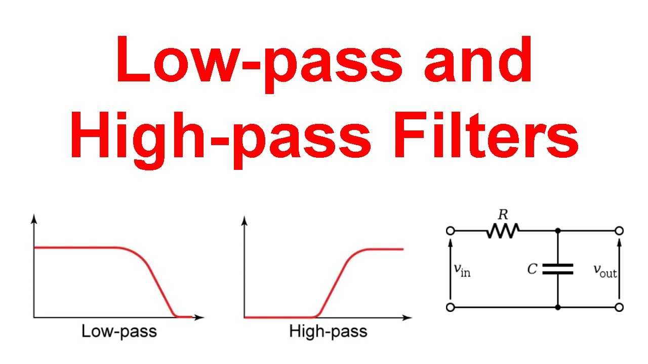
Low-Pass Filters: These allow low-frequency signals to pass while suppressing high-frequency ones. They are highly effective at eliminating noise and interference from signals. For example, low-pass filters can purify sensor outputs by removing high-frequency noise.
High-Pass Filters: These permit high-frequency signals to pass and attenuate low-frequency or DC signals. They are often used for signal pre-enhancement, such as emphasizing edges in image processing or eliminating hum in audio signals.
Band-Pass Filters: These allow signals within a specific frequency range to pass while suppressing those outside this range. They are suitable for applications requiring frequency selection and signal extraction, such as radio receivers tuning to specific stations.
Band-Stop Filters: These suppress signals within a specific frequency band while allowing signals outside the band to pass. They are used in scenarios where blocking a specific frequency range is necessary, such as eliminating power line interference in audio equipment.
All-Pass Filters: These have a flat frequency response and do not attenuate any frequencies. They are used for phase correction, delay, and delay equalization rather than traditional filtering.
Design Techniques and Components:
Passive Filters: Composed of resistors, inductors, and capacitors, these filters contain no active components like transistors or amplifiers. They are simple in structure, cost-effective, and stable, commonly used in RF applications and power supplies.
Active Filters: These include electronic amplification components such as operational amplifiers, enabling the enhancement of weak signals. They are suitable for applications requiring signal amplification and can achieve higher performance and more complex response characteristics compared to passive filters.
Mounting Types:
On-Board Filters: These are directly integrated into circuit boards, used in devices and systems where space and integration are critical considerations.
Panel Filters: Larger and standalone, these filters are typically mounted on racks or panels, separate from the main circuit. They are ideal for applications requiring convenient inspection and maintenance.
Specialized Filters:
Chebyshev Filters: These have ripples in the passband or stopband, providing better control precision within specific frequency ranges. They are suitable for applications needing sharp cutoff characteristics.
Gaussian Filters: These are linear, smooth low-pass filters that use Gaussian functions for weight selection. They effectively remove Gaussian noise and are used for noise reduction in signal or image processing.
Low-Pass Filters
Basic structure: Composed of an op-amp, a resistor, and a capacitor. A common first-order low-pass filter has a simple structure, containing only one op-amp, one resistor, and one capacitor. The op-amp here plays the role of amplification and buffering, making the output of the filter more stable.
Working principle: When the frequency of the input signal is lower than the cutoff frequency, the capacitive reactance is large, and the signal is mainly transmitted through the resistor, outputting almost without attenuation; when the frequency is higher than the cutoff frequency, the capacitive reactance decreases sharply, most of the signal is shunted by the capacitor, and the output signal is significantly attenuated.
Application scenarios: Commonly used in bass enhancement of audio equipment, power supply ripple filtering, etc. For example, in DC power supplies, low-pass filters can filter out AC components to provide a stable DC output.

High-Pass Filters
Basic structure: Also composed of an op-amp, a resistor, and a capacitor, but the connection mode of the capacitor and resistor is different from that of low-pass filters. In a first-order high-pass filter, the capacitor is connected in series in the signal path, and the resistor is grounded.
Working principle: For high-frequency signals, the capacitive reactance is small, so the signal can smoothly pass through the capacitor to the output end; while low-frequency signals are difficult to pass due to the large capacitive reactance, and most of them are grounded through the resistor, thus realizing the suppression of low-frequency signals.
Application scenarios: Widely used in treble adjustment of audio equipment, elimination of DC offset, etc. In audio amplifiers, high-pass filters can remove low-frequency noise in audio signals, making treble clearer.
Band-Pass Filters
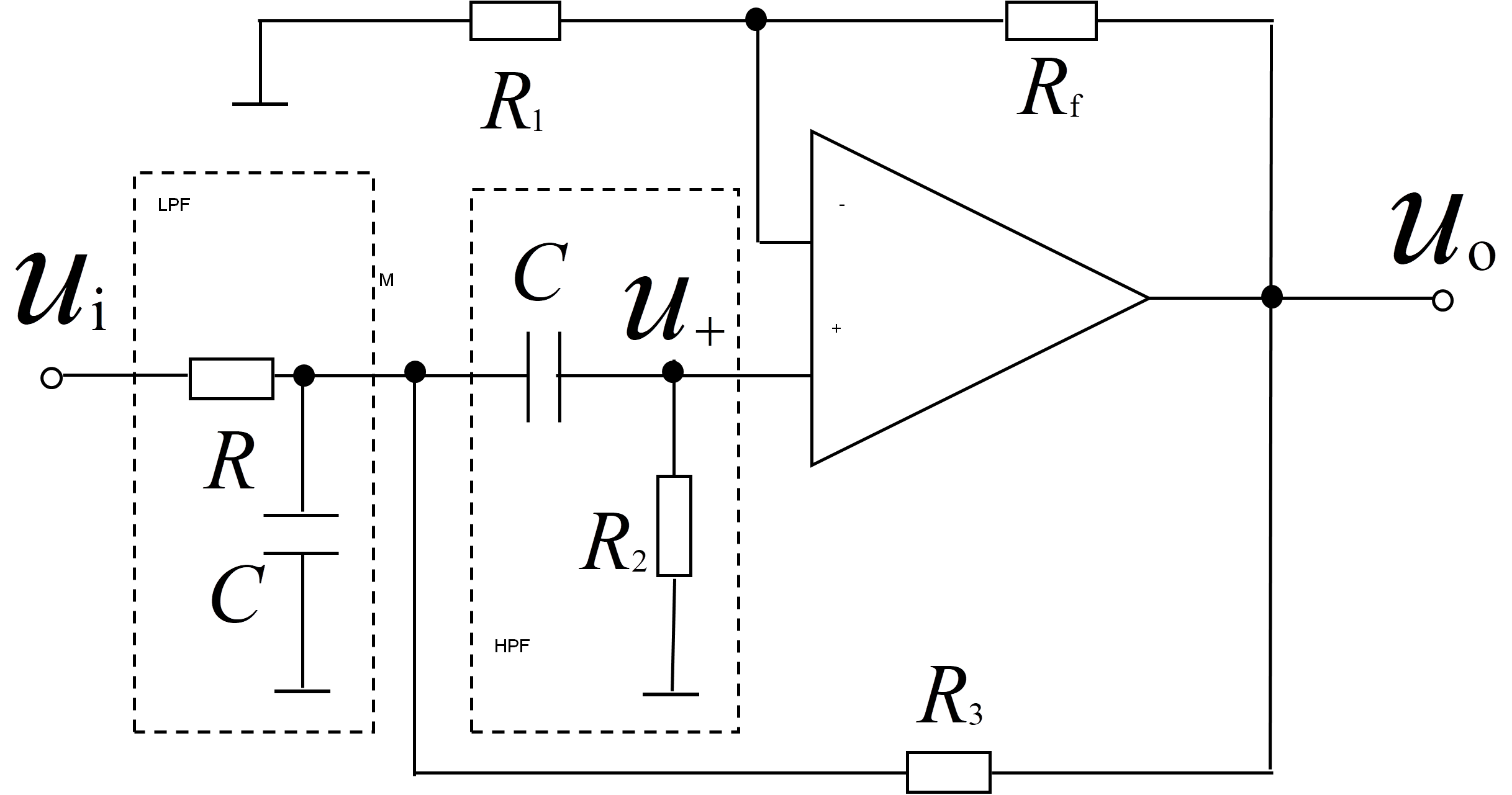
A band-pass filter can allow signals within a specific frequency range to pass. This frequency range is determined by the lower cutoff frequency and the upper cutoff frequency, and the frequency band between them is called the passband.

Bandpass Filter Circuit Diagram
Basic structure: Can be formed by connecting a low-pass filter and a high-pass filter in series. The passband range is determined by reasonably setting the cutoff frequencies of the two filters. The op-amp not only provides amplification function but also combines the characteristics of the two filters well.
Working principle: When the frequency of the input signal is within the passband, it can pass through both the high-pass filter and the low-pass filter, thus outputting smoothly; when the frequency is lower than the lower cutoff frequency, it is suppressed by the high-pass filter; when the frequency is higher than the upper cutoff frequency, it is attenuated by the low-pass filter.
Application scenarios: Used in communication receiving systems to extract carrier signals of specific frequencies; in medical equipment, such as electrocardiographs, to screen out specific frequency components of heart electrical signals.
Band-Stop Filters
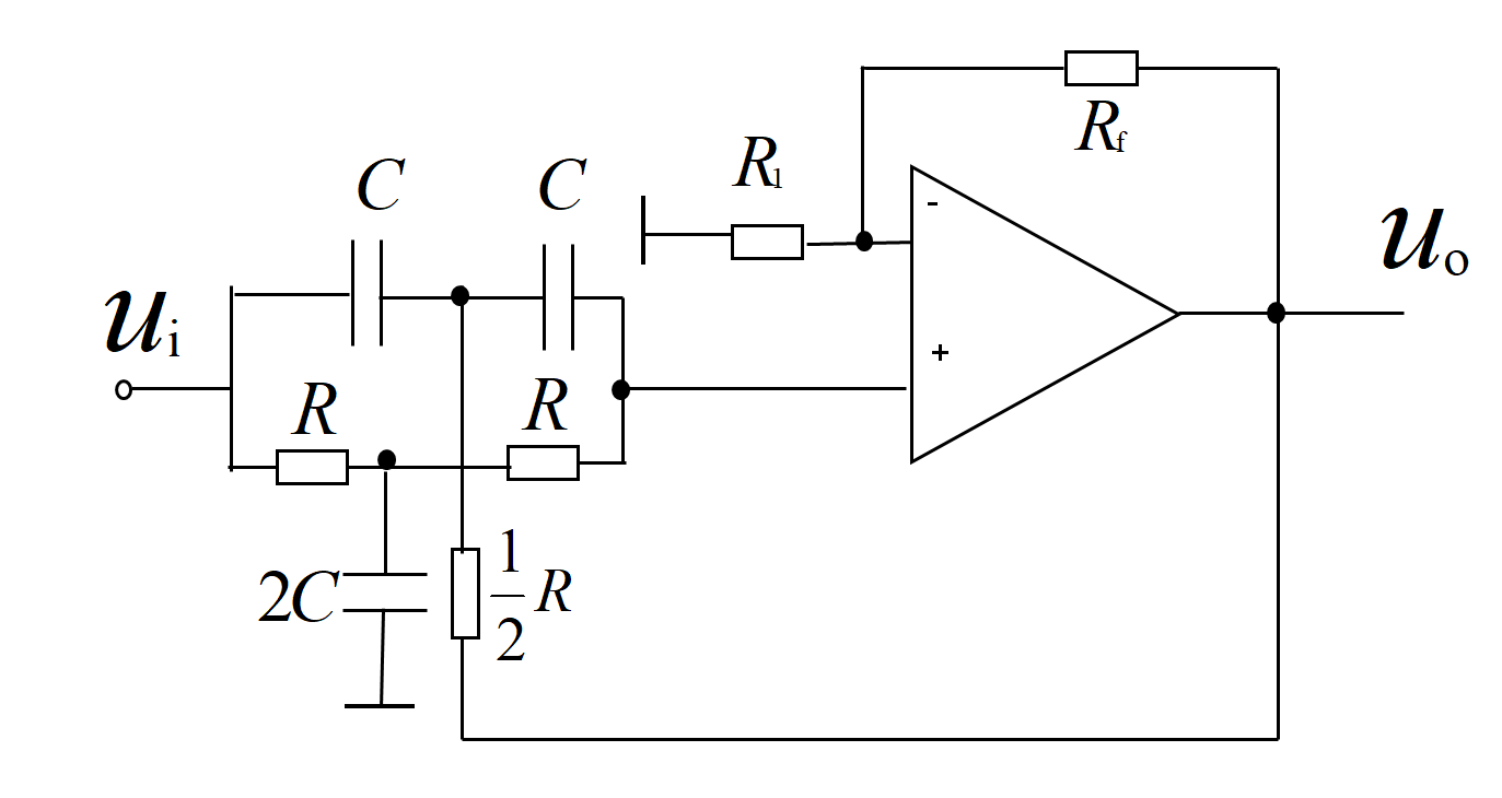
The role of a band-stop filter is to block signals within a specific frequency range, which is also defined by the lower and upper cutoff frequencies, and this frequency band is called the stopband.

Band Stop Filter Circuit Diagram
Basic structure: Usually composed of a low-pass filter and a high-pass filter connected in parallel. The op-amp here plays the role of signal superposition, synthesizing the output signals of the two filters.
Working principle: When the frequency of the input signal is within the stopband, it can pass through neither the low-pass filter nor the high-pass filter, so the output signal is significantly attenuated; when the frequency is lower than the lower cutoff frequency, it can be output through the low-pass filter; when the frequency is higher than the upper cutoff frequency, it can be output through the high-pass filter.
Application scenarios: Mainly used to eliminate interference of specific frequencies, such as filtering out 50Hz or 60Hz power frequency interference in power systems; removing noise of specific frequencies in audio processing.
Conclusion
With the continuous development of electronic technology, the performance requirements for filters are getting higher and higher, such as narrower passbands and steeper roll-off characteristics. In the future, hybrid filters combining digital signal processing technology may become a development trend, further expanding their application fields. Mastering the working principles and design methods of these filters is crucial for electronic engineers, as it can provide a solid foundation for the design and optimization of various electronic systems.
Hot-selling products of SIC
71421LA55J8 UPD44165184BF5-E40-EQ3-A SST39VF800A-70-4C-B3KE IS66WV1M16DBLL-55BLI-TR AS4C32M16SB-7BIN W25Q16FWSNIG
AS7C34098A-20JIN 752369-581-C W957D6HBCX7I TR IS61LPS12836EC-200B3LI MX25L12875FMI-10G QG82915PL
Product information is from SIC Electronics Limited. If you are interested in the product or need product parameters, you can contact us online at any time or send us an email: sales@sic-chip.com.
Operational Amplifier Filters Frequently Asked Questions [FAQ]
Basic Concepts and Classification
What is an operational amplifier filter?
An operational amplifier filter is an electronic circuit composed of an operational amplifier as the core active device, combined with passive components such as resistors and capacitors. It is used to selectively pass or attenuate specific frequency components of the input signal and can be divided into low-pass, high-pass, band-pass, band-stop and other types.
What are the main differences between active filters and passive filters?
Active filters include active components such as operational amplifiers, and have the advantages of controllable gain, strong load capacity, and the ability to achieve steep filtering characteristics without large-volume inductors; passive filters only consist of resistors, inductors, and capacitors, with a simple structure but fixed gain and are greatly affected by the load.
Performance Parameters
What does the cutoff frequency of a filter refer to?
The cutoff frequency refers to the frequency at which the signal power is attenuated by 3dB, which is the boundary dividing the passband and the stopband. For example, the cutoff frequency of a low-pass filter is the critical point where high-frequency signals start to be significantly attenuated.
How does the order of a filter affect its performance?
The order is determined by the number of energy storage components (capacitors, inductors) in the circuit. The higher the order, the steeper the filtering characteristic curve, and the faster the attenuation speed of signals in the stopband (for example, the roll-off speed of a first-order filter is 20dB per decade, and that of a second-order filter is 40dB per decade).
How to measure the selectivity of a filter?
For band-pass and band-stop filters, selectivity can be measured by the quality factor (Q value). The higher the Q value, the narrower the passband (or stopband), and the higher the screening accuracy for specific frequencies.
Design and Application
When designing a low-pass filter, how to select resistor and capacitor values?
It can be calculated according to the target cutoff frequency fc through the formula fc=1/2πRC. For example, if a cutoff frequency of 1kHz is required, a combination of a 15.9kΩ resistor and a 10nF capacitor can be selected (R=1/2πfcC).
Why can high-pass filters eliminate DC offset?
High-pass filters significantly attenuate low-frequency signals (including DC signals with a frequency of 0). DC signals are suppressed because they cannot pass through the series capacitor, thereby eliminating DC offset.
How is the passband range of a band-pass filter determined?
It is jointly determined by the lower cutoff frequency (flow) and the upper cutoff frequency (fhigh). The passband is the frequency range from flow to fhigh, which is usually realized by cascading a high-pass filter (setting flow) and a low-pass filter (setting fhigh).
In what scenarios are band-stop filters most commonly used?
They are mainly used to suppress interference signals of specific frequencies. For example, filtering out 50Hz/60Hz power frequency interference in audio equipment and blocking interference signals of adjacent channels in communication systems.
Practical Usage Issues
Does the supply voltage of the operational amplifier affect the performance of the filter?
Yes, it does. The supply voltage determines the maximum signal amplitude that the filter can handle. If the input signal amplitude exceeds the supply range, it may cause signal distortion; at the same time, the frequency response characteristics of some filters will also change with the supply voltage.
How to reduce noise interference of the filter?
During layout, the signal path should be short and straight, away from high-frequency noise sources; select low-noise operational amplifiers, set reasonable power supply decoupling capacitors; for high-precision applications, shielding measures can be adopted to reduce electromagnetic interference.
How to handle unused operational amplifier pins?
Unused operational amplifier pins should be avoided from being left floating. The non-inverting input can be grounded, the inverting input can be grounded through a resistor, and the output can be short-circuited with the inverting input (forming a unity gain follower) to prevent interference from affecting other circuits.
What is the relationship between the bandwidth of the filter and the signal processing speed?
The wider the bandwidth, the wider the range of signal frequencies that the filter can handle, which is suitable for high-speed signal processing; but an excessively wide bandwidth may introduce more noise, so it is necessary to select a filter with an appropriate bandwidth according to the actual signal frequency range.


 Wishlist (0 Items)