

- RFQ
- BOM
-
Contact Us
Tel: +86-0755-83501315
Email: sales@sic-components.com


- Chinese
- English
- French
- German
- Portuguese
- Spanish
- Russian
- Japanese
- Korean
- Arabic
- Irish
- Greek
- Turkish
- Italian
- Danish
- Romanian
- Indonesian
- Czech
- Afrikaans
- Swedish
- Polish
- Basque
- Catalan
- Esperanto
- Hindi
- Lao
- Albanian
- Amharic
- Armenian
- Azerbaijani
- Belarusian
- Bengali
- Bosnian
- Bulgarian
- Cebuano
- Chichewa
- Corsican
- Croatian
- Dutch
- Estonian
- Filipino
- Finnish
- Frisian
- Galician
- Georgian
- Gujarati
- Haitian
- Hausa
- Hawaiian
- Hebrew
- Hmong
- Hungarian
- Icelandic
- Igbo
- Javanese
- Kannada
- Kazakh
- Khmer
- Kurdish
- Kyrgyz
- Latin
- Latvian
- Lithuanian
- Luxembou..
- Macedonian
- Malagasy
- Malay
- Malayalam
- Maltese
- Maori
- Marathi
- Mongolian
- Burmese
- Nepali
- Norwegian
- Pashto
- Persian
- Punjabi
- Serbian
- Sesotho
- Sinhala
- Slovak
- Slovenian
- Somali
- Samoan
- Scots Gaelic
- Shona
- Sindhi
- Sundanese
- Swahili
- Tajik
- Tamil
- Telugu
- Thai
- Ukrainian
- Urdu
- Uzbek
- Vietnamese
- Welsh
- Xhosa
- Yiddish
- Yoruba
- Zulu
- Kinyarwanda
- Tatar
- Oriya
- Turkmen
- Uyghur
A Comprehensive Guide to Driver ICs
1. Introduction
In the intricate world of electronics, the seamless operation of systems depends on the efficient communication and control between various components. Driver integrated circuits (Driver ICs) have emerged as indispensable elements in this ecosystem, acting as the vital link between control devices, typically microcontrollers, and output devices. Their ability to regulate current or voltage is fundamental in ensuring that output devices function as intended, whether it's powering a simple LED or controlling the complex movements of a robotic arm.
2. Types of Driver ICs
2.1 LED Driver ICs
LEDs have become the standard in lighting applications due to their energy - efficiency and long lifespan. However, to operate optimally, they require precise regulation of current and voltage, which is where LED driver ICs come into play. These ICs are designed to maintain a stable current supply to LEDs, preventing issues such as over - current that can lead to premature failure or inconsistent brightness.
The constant - current type of LED driver ICs is particularly popular. They work by adjusting the voltage across the LED to keep the current flowing through it at a fixed level, regardless of changes in the LED's forward voltage due to temperature variations or manufacturing tolerances. For example, in an automotive headlight system, where the LED's operating temperature can fluctuate significantly, a constant - current LED driver IC ensures that the headlight maintains a consistent brightness, enhancing visibility and safety.
Some advanced LED driver ICs offer additional features like adjustable brightness. This functionality is achieved through techniques such as pulse - width modulation (PWM). By varying the duty cycle of the PWM signal, the average current supplied to the LED can be adjusted, effectively dimming or brightening it. Color - temperature control is another notable feature in certain LED driver ICs. This is especially useful in smart lighting systems, where users can customize the ambiance of a room by adjusting the color temperature of the LED lights, creating a warm and cozy atmosphere or a bright, energizing one.
2.2 Motor Driver ICs
Electric motors are at the heart of countless applications, from the motors that power industrial machinery to the small motors in consumer electronics. Motor driver ICs are responsible for managing the speed, direction, and torque of these motors. They take low - power control signals from a microcontroller and amplify them to the appropriate power levels required by the motor.
Pulse - width modulation (PWM) is a common control method used in motor driver ICs to regulate the speed of motors. By varying the width of the electrical pulses sent to the motor, the average voltage applied to the motor can be adjusted, thereby controlling its speed. For brushed DC motors, motor driver ICs also handle the commutation process, which involves reversing the direction of current flow in the motor windings to keep it rotating.
In the case of brushless DC motors, motor driver ICs are more complex as they need to precisely control the timing of the current applied to each phase of the motor's windings to achieve smooth and efficient operation. Stepper motors, on the other hand, require the motor driver IC to send a series of precisely timed pulses to move the motor in discrete steps. This makes them ideal for applications that require precise positioning, such as 3D printers and CNC machines.
2.3 Display Driver ICs
Display panels, whether they are LCDs, OLEDs, or EL displays, rely on display driver ICs to function properly. These ICs convert digital data, such as images and text, into electrical signals that control the individual pixels or segments of the display. In an LCD display, for example, the display driver IC sends signals to control the voltage applied to the liquid crystal material, which in turn controls the amount of light that passes through the display, creating the visual image.
With the increasing demand for high - resolution and high - refresh - rate displays, display driver ICs have evolved to support these requirements. They now come with features like high - grayscale control, which allows for smooth color transitions and more accurate representation of images. Different interface protocols, such as SPI (Serial Peripheral Interface), I2C (Inter - Integrated Circuit), and LVDS (Low - Voltage Differential Signaling), are supported by display driver ICs to enable efficient communication with the host device, such as a computer or a smartphone.
2.4 Power MOSFET Driver ICs
In high - power applications, such as power supplies for electric vehicles and industrial power systems, Power Metal - Oxide - Semiconductor Field - Effect Transistors (MOSFETs) are commonly used for their high - efficiency and fast - switching capabilities. However, to operate MOSFETs effectively, they require proper gate - drive signals, which is the job of power MOSFET driver ICs.
These driver ICs are designed to provide fast - rising and fast - falling gate - drive signals to ensure that the MOSFETs switch on and off quickly. This reduces power losses during the switching process, improving the overall efficiency of the power conversion system. They also offer precise timing control, which is crucial for applications where accurate switching is required, such as in high - frequency power supplies.
Power MOSFET driver ICs come with built - in protection features against over - voltage and over - current conditions. For example, if an over - voltage situation occurs, the driver IC can quickly shut off the MOSFET to prevent damage. The high gate - drive voltage levels and peak current capacity of these driver ICs are carefully engineered to meet the requirements of different power MOSFETs, ensuring reliable operation in demanding high - power environments.
3. Key Components and Features
Driver ICs consist of several key components that work together to perform their functions. The input stage of a driver IC is responsible for receiving control signals from the microcontroller or other control devices. These signals are then processed by the internal logic circuitry, which interprets the commands and generates the appropriate output signals.
The output stage of the driver IC is where the power amplification occurs. It takes the processed signals from the internal logic and converts them into the high - power signals required to drive the output device. Depending on the type of driver IC, the output stage can have different configurations, such as open - drain, push - pull, or totem - pole, each with its own advantages and applications.
In addition to these basic components, many driver ICs also include additional features such as protection circuits, which safeguard the IC and the connected output device from electrical faults, and diagnostic circuits, which can provide information about the operating status of the driver IC and the output device.
4. Key Considerations for Selecting Driver ICs
4.1 Voltage and Current Ratings
When selecting a driver IC, the voltage and current ratings are among the most critical factors to consider. The input voltage range of the driver IC must be compatible with the output voltage of the control device, while the output voltage and current ratings must be sufficient to meet the requirements of the output device.
For example, if driving a high - power LED array, the driver IC must be able to supply the required current to light up all the LEDs without overheating or exceeding its rated limits. It's also important to consider the peak voltage and current requirements of the output device, especially in applications where there may be sudden surges or transient loads. By carefully matching the voltage and current ratings of the driver IC to the output device, designers can ensure reliable and efficient operation of the electronic system.
4.2 Output Configuration
The output configuration of a driver IC can significantly impact its performance and suitability for a particular application. Open - drain outputs are often used in applications where multiple devices need to share a common line, such as in I2C bus systems. In this configuration, the output transistor can only pull the line low, and an external pull - up resistor is required to pull the line high. This allows multiple devices to communicate on the same line without causing conflicts.
Push - pull outputs, on the other hand, offer better driving capabilities and faster switching speeds. They can source and sink current, which means they can directly drive loads with relatively high currents. This makes them suitable for applications where fast - switching and high - power delivery are required, such as in motor control circuits. Totem - pole outputs are a variation of push - pull outputs that provide even higher current - sinking and sourcing capabilities, making them ideal for applications that demand high - power output, such as in power amplifier circuits.
4.3 Protection Features
Protection features are essential for ensuring the long - term reliability of driver ICs and the connected output devices. Over - current protection is a common feature that limits the current flowing through the driver IC and the output device. This can prevent damage to the components in case of a short - circuit or excessive load.
Over - voltage protection monitors the input and output voltages of the driver IC and protects it from voltage spikes. When an over - voltage condition is detected, the driver IC can either shut down or take appropriate measures to limit the voltage. Thermal protection is also crucial, especially in high - power applications. When the temperature of the driver IC exceeds a certain threshold, the thermal protection circuit will activate, either reducing the power output or shutting down the IC to prevent overheating and potential damage.
4.4 Thermal Management
As mentioned earlier, driver ICs, especially in high - power applications, can generate a significant amount of heat. Effective thermal management is essential to prevent overheating, which can lead to performance degradation and even failure of the IC. Heat sinks are one of the most common thermal management techniques used with driver ICs. They are typically made of materials with high thermal conductivity, such as aluminum or copper, and are designed to increase the surface area of the driver IC, allowing for more efficient heat dissipation.
Thermal vias are another important aspect of thermal management. These are small holes in the printed circuit board (PCB) that are filled with a conductive material, such as copper. They provide a path for heat to transfer from the driver IC to other layers of the PCB, improving the overall heat - dissipation efficiency. Proper overall heat - dissipation efficiency. Proper PCB layout also plays a crucial role in thermal management. By placing the driver IC in an area with good airflow and separating it from other heat - generating components, designers can ensure that the heat generated by the driver IC is dissipated effectively.
4.5 Package Type
The package type of a driver IC can have a significant impact on the design and performance of the electronic system. Different package types offer different advantages in terms of size, thermal performance, and ease of assembly. QFN (Quad Flat No - lead) packages, for example, are popular for their small footprint and good thermal performance. They are suitable for applications where space is limited, such as in portable electronics.
BGA (Ball Grid Array) packages are often used in applications that require a high - density interconnect. They offer a large number of pins in a relatively small area, allowing for complex circuit designs. However, BGA packages can be more challenging to assemble and rework compared to other package types. DIP (Dual In - Line Package) is a more traditional package type that is easy to handle and solder, making it a good choice for prototyping and low - volume production. When selecting a package type, designers need to consider the specific requirements of their application, such as the available space on the PCB, the required thermal performance, and the manufacturing process.
4.6 Cost
Cost is an important consideration in the selection of driver ICs. While high - performance driver ICs with advanced features may offer better functionality, they also come with a higher price tag. Designers need to balance the cost with the performance requirements of the application. In some cases, a less expensive driver IC with basic features may be sufficient to meet the needs of the system, while in other applications, the added performance and features of a more expensive driver IC may be worth the investment.
It's also important to consider the long - term cost implications of the driver IC. This includes factors such as power consumption, reliability, and maintenance. A driver IC with lower power consumption may result in lower operating costs over the lifetime of the product. Similarly, a more reliable driver IC may reduce the need for frequent replacements and maintenance, saving both time and money in the long run.
4.7 Compatibility with Control Systems
For a driver IC to function properly, it must be compatible with the control system or microcontroller it is connected to. This involves ensuring compatibility in terms of communication interfaces, voltage levels, and timing requirements. Different driver ICs support various communication interfaces, such as SPI, I2C, or UART. The control system must be able to communicate with the driver IC using the same interface protocol.
In addition to the communication interface, the voltage levels of the control signals from the microcontroller must be compatible with the input requirements of the driver IC. If the voltage levels are not compatible, additional circuitry may be required to level - shift the signals. Timing requirements are also crucial, especially in applications where precise control is needed. The control system must be able to generate control signals at the correct timing intervals to ensure that the driver IC operates as intended.
4.8 Adherence to Safety Standards
Driver ICs used in consumer and industrial applications must comply with relevant safety standards. Electrical safety standards, such as those set by UL (Underwriters Laboratories) and CE (Conformité Européene), ensure that the driver IC does not pose a risk of electric shock or fire. Electromagnetic compatibility (EMC) standards are also important, as compatibility (EMC) standards are also important, as they ensure that the driver IC does not interfere with other electronic devices in the vicinity and is not affected by external electromagnetic interference.
Environmental regulations, such as RoHS (Restriction of Hazardous Substances), restrict the use of certain hazardous materials in electronic components. Driver ICs that comply with these standards are safer for both the environment and the end - user. Certification by recognized standards organizations indicates that the driver IC meets the required safety and performance criteria, giving designers and consumers confidence in the product's reliability.
5. Evaluating and Testing Driver ICs
5.1 Reviewing Datasheets and Application Notes
The datasheet is the primary source of information about a driver IC. It contains detailed specifications, such as electrical characteristics, recommended operating conditions, and pin - out diagrams. By carefully reviewing the datasheet, designers can determine if the driver IC meets the requirements of their application. For example, they can check the voltage and current ratings, power dissipation, and switching times to ensure that the IC is suitable for the intended output device.
Application notes, on the other hand, provide practical guidance on how to use the driver IC in specific applications. They often include circuit diagrams, design examples, and troubleshooting tips. Application notes can be particularly helpful for designers who are new to using a particular driver IC or who are working on a complex application. By referring to the application notes, designers can avoid common pitfalls and ensure that they are using the driver IC in the most effective way possible.
5.2 Prototype Testing
Building a prototype circuit using the driver IC is an essential step in evaluating its performance. In the prototype stage, designers can test the driver IC under real - world conditions, including different load conditions and input signals. This allows them to identify any issues or challenges that may arise in the actual application, such as electrical interference, thermal problems, or compatibility issues with other components.
During prototype testing, various parameters of the driver IC can be measured and analyzed. For example, the output voltage and current can be measured using an oscilloscope and a multimeter to ensure that they are within the specified range. The temperature of the driver IC can also be monitored using a thermal camera or a temperature sensor to check for any overheating issues. Based on the results of the prototype testing, designers can make adjustments to the circuit design or select a different driver IC if necessary.
5.3 Seeking Recommendations and Reviews
Feedback from other engineers or users who have experience with a particular driver IC can be invaluable. Online forums, technical blogs, and product review websites are good sources of user - generated content. By reading reviews and participating in discussions, designers can learn about the real - world performance, reliability, and ease of use of the driver IC.
Professional engineering communities and industry events also provide opportunities to interact with other engineers and share experiences. Attending conferences and seminars, or joining engineering groups on social media platforms, can help designers stay updated on the latest trends and best practices in driver IC design and selection. Recommendations from trusted colleagues or industry experts can also help designers make more informed decisions when choosing a driver IC for their projects.
6. Advantages and Challenges of Using Driver ICs
6.1 Advantages
One of the key advantages of using driver ICs is improved efficiency. By precisely regulating the power delivered to the output device, driver ICs can ensure that the device operates at its optimal efficiency. In LED lighting applications, for example, an LED driver IC can prevent over - driving the LEDs, which not only reduces power consumption but also extends the lifespan of the LEDs.
Driver ICs also help in reducing the component count in a circuit. Instead of using multiple discrete components to perform functions such as amplification, protection, and control, a single driver IC can integrate all these functions. This simplifies the circuit design, reduces the overall cost of the system, and saves valuable board space. In addition, a reduced component count can also improve the reliability of the system, as there are fewer components that can potentially fail.
Another significant advantage is enhanced system performance. Driver ICs offer precise control over the output device, which can lead to better performance in terms of speed, accuracy, and stability. In motor control applications, motor driver ICs can provide accurate speed and torque control, resulting in smoother operation of the motor and improved performance of the overall system. In display applications, display driver ICs can ensure high - quality image reproduction with accurate color representation and fast refresh rates.
6.2 Challenges
Despite their many advantages, driver ICs also present some challenges. Thermal management is a major issue, especially in high - power applications. As driver ICs dissipate heat during operation, if not properly managed, this heat can cause the IC to overheat, leading to performance degradation or even failure. Designers need to carefully consider thermal management techniques, such as using heat sinks, thermal vias, and proper PCB layout, to ensure that the driver IC operates within its specified temperature range.
Electromagnetic interference (EMI) and electromagnetic compatibility (EMC) are also concerns when using driver ICs. Driver ICs can generate EMI, which can interfere with the operation of other electronic components in the system. At the same time, they may also be susceptible to EMC issues, such as being affected by external electromagnetic fields. To address these issues, designers need to implement shielding, filtering, and proper grounding techniques to minimize EMI emissions and ensure EMC compliance.
6.3 Strategies for Overcoming Challenges
To overcome thermal management challenges, effective thermal design is crucial. Using high - quality heat sinks with a large surface area and good thermal conductivity can significantly improve heat dissipation. Thermal vias can be strategically placed in the PCB to enhance heat transfer between different layers. Ensuring sufficient airflow around the driver IC, either through natural convection or using fans, can also help in cooling the IC. Additionally, using thermal interface materials, such as thermal paste or pads, between the driver IC and the heat sink can improve the thermal contact and further enhance heat dissipation.
For EMI/EMC concerns, implementing shielding techniques is an effective strategy. Shielding cans can be used to enclose the driver IC and prevent EMI from escaping orentering the IC. Ferrite beads can be added to the power and signal lines to filter out high - frequency noise and reduce EMI emissions. Proper PCB layout is also essential. Signal routing should be carefully planned to minimize the length of high - frequency traces and avoid creating loops that can act as antennas for EMI. Grounding should be done correctly, with a single - point or multi - point grounding strategy depending on the circuit requirements, to ensure that electrical noise is effectively drained away.
In addition, selecting driver ICs with built - in EMI/EMC mitigation features can simplify the design process. Some modern driver ICs come with integrated shielding structures or advanced internal circuitry that helps in reducing EMI emissions and improving EMC immunity. By leveraging these features along with proper design techniques, designers can effectively address EMI/EMC challenges and ensure the reliable operation of the electronic system.
7. Future Trends in Driver IC Technology
7.1 Integration of Advanced Features
The future of driver ICs lies in the integration of advanced features that will revolutionize the way electronic systems operate. Adaptive control mechanisms are set to become a standard feature in driver ICs. These mechanisms will enable the ICs to sense changes in the operating conditions of the output device, such as variations in load, temperature, or input signals, and automatically adjust the control parameters to optimize performance. For example, in a motor control application, an adaptive - control - enabled driver IC can detect changes in the motor's load and adjust the voltage and current supplied to it in real - time, ensuring smooth operation and maximum efficiency.
Artificial intelligence (AI) algorithms are also on the verge of being integrated into driver ICs. AI - enabled driver ICs will be able to learn from historical data and patterns to predict potential issues and make proactive adjustments. In a smart lighting system, an AI - powered LED driver IC can analyze the usage patterns of the lights, such as the time of day, occupancy, and ambient light levels, and adjust the brightness and color temperature of the LEDs accordingly, providing an optimal lighting experience while minimizing energy consumption.
Predictive maintenance and self - diagnosis features will also become increasingly important. Driver ICs will be able to continuously monitor their own health and the status of the connected output devices. By detecting early signs of component degradation, such as changes in electrical characteristics or abnormal temperature increases, the IC can alert the system or initiate self - corrective actions. This will significantly reduce downtime in industrial applications and improve the overall reliability of consumer electronics.
7.2 Miniaturization
The relentless demand for smaller and more compact electronic devices is driving the miniaturization of driver ICs. As consumer electronics, such as smartphones, smartwatches, and wireless earbuds, continue to shrink in size, driver ICs need to follow suit to fit into these ultra - thin form factors. Manufacturers are investing heavily in research and development to reduce the size of driver ICs without sacrificing performance.
Advanced semiconductor manufacturing processes, such as nanometer - scale fabrication techniques, are enabling the creation of smaller and more integrated driver ICs. These processes allow for the reduction of the physical size of the transistors and other components on the chip, resulting in a smaller die size. Additionally, new packaging technologies, such as chip - on - board (COB), system - in - package (SiP), and fan - out wafer - level packaging (FOWLP), are being developed to further minimize the footprint of driver ICs.
However, miniaturization also poses several challenges. Heat dissipation becomes even more critical in smaller packages, as the limited surface area available for heat transfer can lead to higher operating temperatures. Electrical performance can also be affected, as the closer proximity of components can increase the risk of crosstalk and signal interference. To overcome these challenges, innovative thermal management solutions, such as micro - heat pipes and phase - change materials, are being explored. Advanced circuit design techniques, including differential signaling and impedance matching, are also being employed to ensure reliable electrical performance in miniaturized driver ICs.
7.3 Enhanced Functional Safety
In safety - critical applications, such as automotive, aerospace, and medical devices, the demand for enhanced functional safety features in driver ICs is growing rapidly. Driver ICs for these applications need to meet strict safety standards, such as ISO 26262 for automotive electronics and IEC 62304 for medical device software. To comply with these standards, driver ICs will incorporate built - in diagnostics, fault - detection mechanisms, and fail - safe strategies.
For example, in an automotive power steering system, the motor driver IC will be equipped with multiple layers of diagnostic functions to continuously monitor the operation of the motor and the IC itself. If a fault is detected, such as an open - circuit in the motor windings or an over - temperature condition in the IC, the driver IC will immediately take appropriate actions, such as reducing the power output or shutting down the system to prevent a potential safety hazard.
Fail - safe mechanisms will ensure that the driver IC and the connected output device enter a safe state in the event of a failure. This may involve setting the output to a predefined safe level, disconnecting the power supply, or sending an alert to the system's control unit. As safety - critical applications become more complex and autonomous, the role of driver ICs in ensuring functional safety will become even more crucial, driving the development of more advanced safety - related features and technologies.
8. Conclusion
8.1 Recap of Key Points
Driver ICs are the unsung heroes of electronic systems, acting as the vital link between control devices and output devices. Their diverse types, including LED driver ICs, motor driver ICs, display driver ICs, and power MOSFET driver ICs, each serve unique functions and find applications in a wide range of industries. From regulating the current to LEDs for efficient lighting to controlling the speed and direction of motors in industrial automation, driver ICs play an indispensable role in ensuring the proper operation of electronic devices.
Selecting the right driver IC is a complex process that requires careful consideration of multiple factors. Voltage and current ratings, output configuration, protection features, thermal management, package type, cost, compatibility with control systems, and adherence to safety standards all need to be evaluated. Moreover, thorough evaluation and testing, through methods such as reviewing datasheets, prototype testing, and seeking recommendations, are essential to guarantee the performance and reliability of the chosen driver IC.
8.2 Future Outlook
The future of driver IC technology is filled with exciting possibilities. The integration of advanced features like adaptive control, AI, predictive maintenance, and self - diagnosis will make driver ICs more intelligent and efficient, enabling the development of smarter and more autonomous electronic systems. Miniaturization efforts will continue to drive the creation of smaller and more powerful driver ICs, meeting the ever - increasing demand for compact electronic devices.
Enhanced functional safety features will ensure that driver ICs can be used with confidence in safety - critical applications, further expanding their scope of use. As technology continues to evolve, driver ICs will remain at the forefront of innovation in the electronics industry, playing a pivotal role in shaping the future of consumer electronics, automotive, industrial automation, and many other sectors. Their continuous development and improvement will be essential for the advancement of modern technology and the creation of more sophisticated, reliable, and user - friendly electronic products.
Driver ICs FAQ:
What is a Motor Drive IC?
A Motor Drive IC is an integrated circuit designed to control electric motors. It acts as an interface between a microcontroller or other control device and the motor, translating control signals into the appropriate electrical signals to drive the motor. These ICs are crucial for regulating the speed, direction, and torque of motors in various applications. For example, in a robotic arm, a motor drive IC enables precise control of the motors, allowing for accurate movement.
What is the Function of Motor Drive IC?
The primary functions of a motor drive IC include providing the necessary power to the motor, controlling the motor's speed, direction, and torque. It can convert low - power control signals from a microcontroller into high - power signals suitable for driving the motor. For instance, it can generate pulse - width - modulated (PWM) signals to vary the speed of a DC motor. In addition, it often includes protection features such as over - current protection, over - voltage protection, and thermal protection to safeguard the motor and itself from damage.
What are the Advantages of Driver ICs?
Driver ICs offer several advantages. They simplify the design process by integrating multiple functions into a single chip, reducing the need for external components. This leads to a smaller circuit footprint and lower cost. They also improve system performance by providing precise control over the connected devices. For example, in a display application, a driver IC ensures accurate pixel control, resulting in better image quality. Additionally, driver ICs often have built - in protection features, enhancing the reliability and safety of the system.
Are there Disadvantages of Driver ICs?
One potential disadvantage of driver ICs is their limited power handling capacity in some cases. High - power applications may require multiple driver ICs or more complex configurations. Another issue is that they can be sensitive to voltage fluctuations and electromagnetic interference (EMI), which may require additional measures for proper operation. Moreover, if a driver IC fails, it can cause the entire system to malfunction, and in some cases, replacement can be costly and time - consuming.
How do you Choose Suitable Motor Driver IC?
When choosing a suitable motor driver IC, several factors need to be considered. First, the voltage and current requirements of the motor must match the ratings of the driver IC. For example, if the motor requires a high voltage and current, a driver IC with appropriate power handling capabilities should be selected. The type of motor (such as DC, stepper, or brushless DC) also determines the choice, as different motors require different control signals. Additionally, features like protection functions, communication interfaces (e.g., SPI, I2C), and the ability to operate in specific environmental conditions should be taken into account.
What is a Motor Drive?
A motor drive is a system that controls the operation of an electric motor. It typically includes a motor drive IC, power supply components, and other associated circuitry. The motor drive takes input signals, such as control commands from a microcontroller, and converts them into electrical signals to drive the motor. It can adjust the motor's speed, direction, and torque according to the requirements of the application. For example, in an electric vehicle, the motor drive system controls the rotation of the electric motor to power the vehicle.
How do you Specify IC Motor Driver?
To specify an IC motor driver, one must consider the motor's electrical characteristics, including voltage, current, and power requirements. The type of motor (e.g., brushed DC, brushless DC, stepper) is also crucial. Other factors include the control interface (e.g., analog, digital, PWM), the required protection features (such as over - current, over - voltage, and thermal protection), and the operating environment (temperature range, humidity). Additionally, the size, cost, and availability of the driver IC should be considered.
What are the Components of Driver ICs?
Driver ICs typically contain input/output pins for connecting to the control device and the load (such as a motor), amplifiers to boost the control signals to the appropriate power level, voltage regulators to maintain a stable output voltage, and protection circuits to prevent damage from over - current, over - voltage, and other faults. Some driver ICs may also include additional features like pulse - width modulation (PWM) generators for speed control and logic circuits for signal processing.
How much does the Motor Drive IC cost?
The cost of a motor drive IC can vary widely depending on factors such as its power rating, functionality, brand, and the number of channels. Simple, low - power motor drive ICs can cost a few dollars, while high - power, multi - channel ICs with advanced features may cost upwards of tens of dollars. For example, a basic single - channel DC motor driver IC for low - power applications might cost around $2 - $5, while a high - end driver IC for a three - phase brushless DC motor in an industrial application could cost $20 - $50.
What are the common problems with Motor Control Units?
Common problems with motor control units include overheating, which can be caused by high - current operation or poor heat dissipation. Over - current and over - voltage issues can also damage the control unit. Electrical interference from other components in the system can disrupt the control signals, leading to erratic motor behavior. Additionally, mechanical wear and tear of the motor can cause problems for the control unit, as it may need to adjust its control signals to compensate for changes in the motor's performance.
How many Types of Motor Drives are there?
There are several types of motor drives, mainly classified according to the type of motor they control. For DC motors, there are brushed DC motor drives and brushless DC motor drives. Stepper motor drives are designed specifically for stepper motors. In addition, there are AC motor drives for controlling alternating - current motors, which can be further divided into types for induction motors and synchronous motors. Each type of drive has its own characteristics and is suitable for different applications.
What is a Brushed DC Motor Driver IC?
A brushed DC motor driver IC is an integrated circuit designed to control brushed DC motors. It provides the necessary power and control signals to drive the motor. These ICs can control the motor's speed by adjusting the voltage applied to the motor, often using pulse - width modulation (PWM). They also manage the direction of rotation by reversing the polarity of the voltage. For example, in a small fan or a toy car, a brushed DC motor driver IC is used to control the motor's operation.
What is L293D?
The L293D is a popular dual - H - bridge motor driver IC. It can control two DC motors simultaneously or a single stepper motor. It has the ability to drive motors with a relatively high current, up to 600mA per channel. The L293D is widely used in robotics and other hobby - level projects due to its simplicity and affordability. It can be easily interfaced with microcontrollers to control the speed and direction of motors.
What is the Function of IC L293D?
The L293D's main function is to drive DC motors or stepper motors. It can control the speed of the motors by varying the duty cycle of the input PWM signals. For direction control, it can reverse the voltage applied to the motor windings. It has built - in protection features to prevent damage from over - current. Each of its two H - bridge sections can independently control the speed and direction of a connected motor, making it suitable for applications that require multiple motor control, such as differential - drive robots.
What are the functions of the 16 Pins in Driver ICs?
The functions of the 16 pins in a driver IC like the L293D vary. Generally, there are power supply pins to provide the necessary voltage for the IC and the motor. Input pins receive control signals from a microcontroller, such as PWM signals for speed control and direction control signals. Output pins are connected to the motor windings to supply the driving voltage. There are also ground pins for electrical connection and stability. Some pins may be used for enabling or disabling the driver, and in some cases, for thermal protection or other special functions.
Why do you need a Motor Drive IC?
A motor drive IC is needed because motors often require higher power levels than what a microcontroller or other control devices can directly provide. It serves as an interface to translate the low - power control signals from a microcontroller into high - power signals suitable for driving the motor. It also provides protection features to safeguard the motor and the control system from electrical faults, such as over - current and over - voltage. Additionally, it simplifies the design process by integrating multiple functions related to motor control into a single chip.
How does Drive IC Operate?
A drive IC operates by receiving control signals, usually from a microcontroller. These signals are then processed and amplified within the IC. For example, if it is a motor drive IC, the control signals may be used to generate PWM signals to control the speed of the motor. The IC also manages the power supply to the motor, ensuring that the appropriate voltage and current are provided. In the case of a display driver IC, it takes digital data from the control device and converts it into signals to control the individual pixels or segments of the display.
What is the importance of 4 Grounds in Driver IC?
The 4 grounds in a driver IC serve several important purposes. They provide a common electrical reference point for all the components within the IC, ensuring proper electrical functioning. Multiple grounds help in reducing electrical noise and interference, which can affect the performance of the IC and the connected devices. They also play a crucial role in dissipating heat, especially in high - power applications. In some cases, different grounds may be used for different functions, such as power ground and signal ground, to minimize cross - talk between different parts of the circuit.
What are the Types of Driver ICS?
There are several types of driver ICs. Motor driver ICs are used to control electric motors, as mentioned before. Display driver ICs are designed for controlling displays, such as LCDs, OLEDs, and LED displays. LED driver ICs are specifically for driving LEDs, regulating the current and voltage to ensure proper brightness and operation. Power MOSFET driver ICs are used to control Power Metal - Oxide - Semiconductor Field - Effect Transistors (MOSFETs) in high - power applications. Sensor driver ICs interface with sensors, conditioning and amplifying the sensor signals for further processing.
What is the Role of a Capacitor in Motor Driver ICs?
Capacitors in motor driver ICs have multiple roles. They are used for power supply decoupling, which helps in filtering out high - frequency noise from the power supply. This ensures a stable power supply for the IC and the motor, preventing electrical interference. Capacitors can also be used in timing circuits, for example, in the generation of PWM signals. In some cases, they are used for energy storage, especially in applications where the motor may require sudden bursts of power.
How do you Test Motor Driver IC?
To test a motor driver IC, one can first check the power supply connections to ensure the correct voltage is being supplied. Then, input control signals, such as PWM signals, can be applied to the input pins of the IC while monitoring the output pins connected to the motor. The motor's speed and direction should change according to the input signals. Measuring the current flowing through the motor can also help in detecting any abnormal behavior. Additionally, using an oscilloscope to check the waveforms at the input and output pins can provide valuable information about the IC's operation.
What is Gate Driver IC?
A gate driver IC is a type of driver IC that is specifically designed to control the gates of power semiconductor devices such as MOSFETs and IGBTs (Insulated - Gate Bipolar Transistors). Its main function is to provide the necessary voltage and current to turn these devices on and off rapidly and efficiently. This is crucial in high - power applications, as proper gate driving can improve the performance and efficiency of the power conversion circuit and protect the power devices from damage.
Are there Special Function Motor Driver ICs?
Yes, there are special function motor driver ICs. For example, some motor driver ICs are designed for specific types of motors, like linear motor driver ICs for linear motors. There are also motor driver ICs with built - in motion control algorithms, which can simplify the design of complex motion control systems. Some special function motor driver ICs are optimized for low - power applications, reducing power consumption while still providing adequate motor control.
What are H - bridge Driver ICs?
H - bridge driver ICs are a type of motor driver IC used to control the direction of DC motors. They consist of four switching elements (usually transistors) arranged in an H - shaped configuration. By controlling the switching of these elements, the H - bridge can reverse the polarity of the voltage applied to the motor, thereby changing the motor's direction of rotation. H - bridge driver ICs are also used in some applications to control the speed of the motor by varying the duty cycle of the applied voltage using PWM.
How does a Stepper Motor Driver IC Work?
A stepper motor driver IC works by sending a series of pulses to the motor windings in a specific sequence. Each pulse causes the motor to rotate a fixed angle, known as a step. The IC controls the number of pulses, the frequency of the pulses, and the sequence in which they are sent to control the speed and position of the stepper motor. Some stepper motor driver ICs also support micro - stepping, which allows for more precise control of the motor's position by dividing each full step into smaller sub - steps.
What makes Haptic Feedback Driver ICs Unique?
Haptic feedback driver ICs are unique in that they are designed to generate tactile sensations or vibrations for user feedback. They can precisely control the intensity, frequency, and duration of the haptic feedback. These ICs are often used in touch - screen devices, gaming controllers, and wearable devices. Unlike other driver ICs, they focus on creating a physical sensation rather than simply controlling the operation of a motor or display. They can provide a more immersive user experience by simulating different textures, impacts, or other tactile effects.
How many types of Electric Motors are there?
There are several types of electric motors. The main categories include DC motors (which can be further divided into brushed DC motors and brushless DC motors), AC motors (such as induction motors and synchronous motors), and stepper motors. Each type has its own characteristics, advantages, and applications. For example, brushed DC motors are simple and inexpensive, while brushless DC motors are more efficient and have a longer lifespan. Induction motors are widely used in industrial applications, and stepper motors are known for their precise position control.
How does MOSFET Gate Driver Work?
A MOSFET gate driver works by providing the necessary voltage and current to the gate of a MOSFET. When a positive voltage is applied to the gate, the MOSFET turns on, allowing current to flow between the source and the drain. The gate driver ensures that the gate - source voltage is within the specified range for proper operation. It can also control the rise and fall times of the gate voltage, which affects the switching speed of the MOSFET. In high - power applications, the gate driver needs to supply sufficient current to charge and discharge the gate - source capacitance of the MOSFET quickly, reducing power losses during switching.
How does High Side Switching compare to Low Side Switching?
High - side switching refers to switching the positive supply voltage to the load, while low - side switching involves switching the ground connection to the load. High - side switching is more complex because it requires additional circuitry to sense and control the voltage at the high - side terminal. It is often used when the load needs to be connected to the positive supply for proper operation, such as in some power - amplifier circuits. Low - side switching is simpler and more commonly used in many applications. However, in some cases, high - side switching can offer better protection and isolation, especially when dealing with sensitive loads.
How do you Control Motor with a Relay?
To control a motor with a relay, the relay is connected in series with the motor and the power supply. When the relay is energized (by applying a control signal to its coil), the contacts close, allowing current to flow through the motor and start it. To control the motor's direction, a double - pole double - throw (DPDT) relay can be used. By switching the relay contacts, the polarity of the voltage applied to the motor can be reversed, changing the motor's direction. However, relays have limitations such as slow switching speeds and a limited number of switching cycles compared to solid - state motor control devices.
How does Driver Circuit Work for an IGBT?
An IGBT (Insulated - Gate Bipolar Transistor) driver circuit works by providing the appropriate gate - drive signals to the IGBT. The driver circuit takes a low - power control signal from a microcontroller or other control device and amplifies it to a level sufficient to turn the IGBT on and off. It ensures that the gate - emitter voltage of the IGBT is within the proper range for reliable operation. The driver circuit also includes protection features such as over - current protection and short - circuit protection. When an over - current or short - circuit condition is detected, the driver circuit quickly turns off the IGBT to prevent damage.
What is a Motor Driver Shield?
A motor driver shield is a printed circuit board (PCB) that contains a motor driver IC and other associated components, such as capacitors, resistors, and sometimes opto - isolators. It is designed to be easily connected to a microcontroller development board, like an Arduino board. The shield simplifies the process of adding motor control capabilities to a project by providing a ready - made interface for connecting motors. It also often includes features like screw - terminal connectors for easy motor wiring and power supply connections.
What is the Function of Buffer in Motor ICs?
In motor ICs, a buffer is used to isolate and amplify signals. It takes an input signal, such as a control signal from a microcontroller, and amplifies it to a level that can drive the motor or other components in the motor control circuit. Buffers also help in impedance matching, ensuring that the output of one circuit stage can properly drive the input of the next stage. They can prevent signal degradation and improve the overall performance of the motor control system by providing a clean and amplified signal.
https://www.sic-components.com/motors-actuators-solenoids-and-drivers

Hot Products
View More-
74LVXC4245MTR STMicroelectronics
-

PIC24HJ64GP204-E/PT Microchip Technology
-
AD5307BRUZ-REEL Analog Devices Inc.
-
LTC3811EUHF#PBF Analog Devices Inc.
-
TL074CN Texas Instruments
-
LT1767EMS8#TRPBF Analog Devices Inc.
-
X9116WS8-2.7 Renesas Electronics America Inc
-
MAX6442KAOSRD3+T Analog Devices Inc./Maxim Integrated
-
DAC08CP Analog Devices Inc.
-

NJM2296D# Nisshinbo Micro Devices Inc.
-
PCI1515GHK Texas Instruments
-
S-80154BLPF-JFFTFG ABLIC Inc.
Related Blogs
-
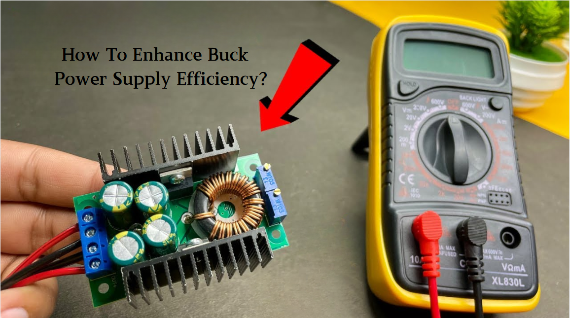
2025 / 06 / 26
Key Strategies to Enhance Buck Power Supply Efficiency
Improving the efficiency of Buck (step-down) switching power supplies requires a multi-dimensional approach targeting energy loss sources, including component selection, topology optimization, control strategies, and thermal management. Below are core strategies and engineering practices:...
-
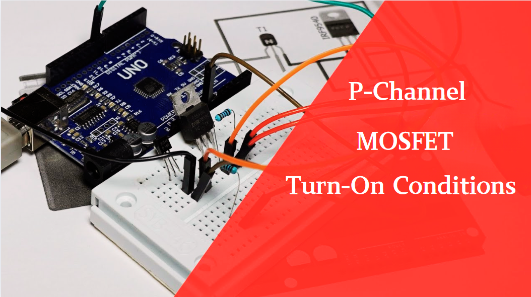
2025 / 06 / 26
P-Channel MOSFET Turn-On Conditions
The turn-on conditions for a P-channel MOSFET (PMOS) are inverse to those of an N-channel MOSFET (NMOS), primarily governed by the relationship between the gate-source voltage (VGS) and the threshold voltage (Vth), along with voltage polarity. Here are the key points:A PMOS turns on when its gate vo...
-
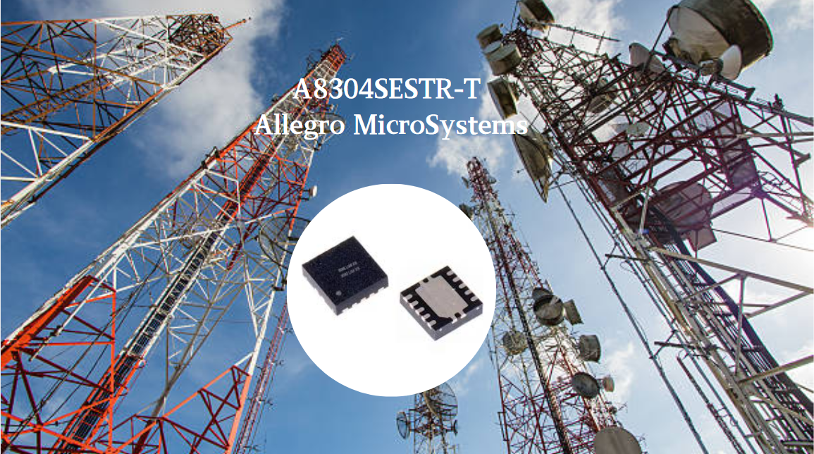
2025 / 06 / 24
A8304SESTR-T Allegro MicroSystems-Single LNB Supply and Control Voltage Regulator
The Allegro MicroSystems A8304SESTR-T is a single-channel Low Noise Block Regulator (LNBR). It integrates a monolithic boost converter with MOSFET, current sensing, and compensation. Featuring a 704 kHz switching frequency, it uses few external components. With an I²C-compatible interface, it offers...
-
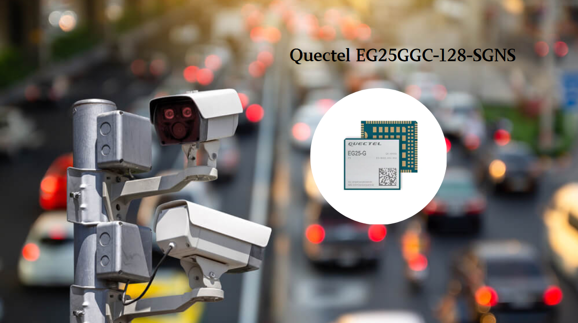
2025 / 06 / 20
EG25GGC-128-SGNS by Quectel Wireless Solutions Co., Ltd: Features,Symbol,Footprint and Datasheet
The Quectel EG25GGC - 128 - SGNS is an LTE Cat 4 module optimized for M2M and IoT. Supporting 3GPP Rel. 11, it offers up to 150Mbps downlink and 50Mbps uplink. With global LTE/UMTS/GSM coverage, it's backward - compatible with EDGE/GPRS. Featuring multi - constellation GNSS (GPS, GLONASS, BeiDou, et...
-
2025 / 06 / 17
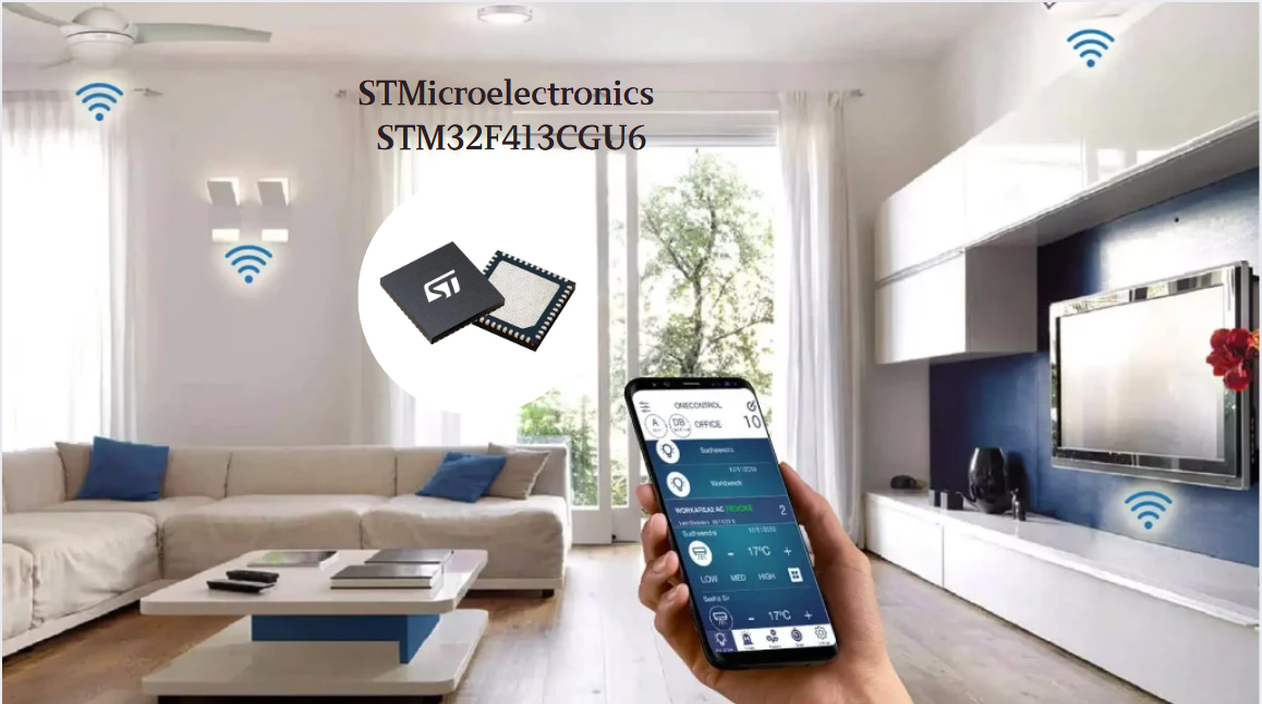
STMicroelectronics STM32F413CGU6 Microcontroller: Datasheet, Performance, Features
The STMicroelectronics STM32F413CGU6 is an Arm® Cortex®-M4 based MCU with FPU, operating at up to 100 MHz for 125 DMIPS performance. It features 1MB Flash, 320KB SRAM, and interfaces like USB OTG FS, 3 CAN, ADC, 2 DAC, and multiple serial ports. With low-power modes (Sleep, Stop, Standby), it suits ...
-
2025 / 06 / 13
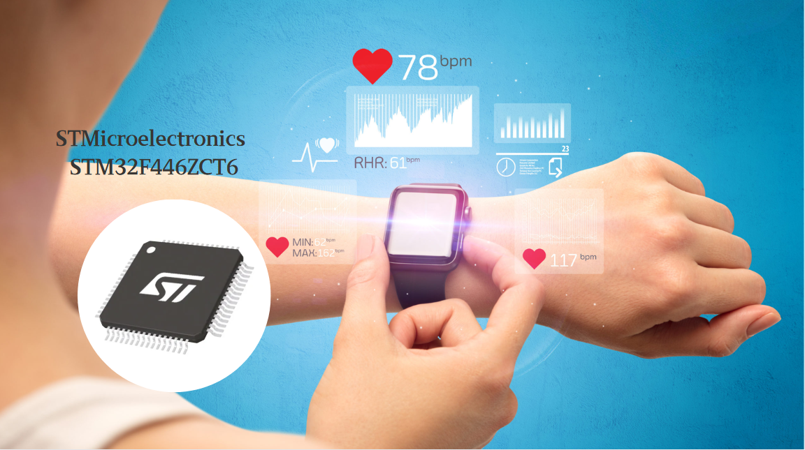
STMicroelectronics STM32F446ZCT6 -Microcontrollers: A Comprehensive Guide
The STMicroelectronics STM32F446ZCT6 is an ARM Cortex-M4-based MCU with FPU, running at up to 180 MHz. It features 256 KB Flash, 128 KB SRAM + 4 KB backup SRAM, and offers rich peripherals: USB OTG HS/FS, 2 CAN, 3 ADCs, 17 timers, and 20 communication interfaces. In LQFP144 package, industrial temp ...
-
2025 / 06 / 09
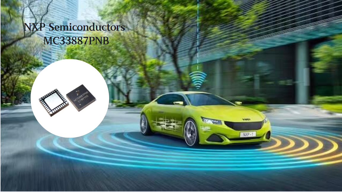
MC33887PNB NXP Semiconductors-Motor Drivers:A Comprehensive Guide
The NXP Semiconductors MC33887PNB is a 5.0 A H - bridge power IC with integrated load current feedback. It operates across a 5.0 V - 28 V voltage range, features low RDS(on) (120 mΩ typical), and supports up to 10 kHz PWM. With functions like active current limiting and fault reporting, it ensures r...
-
2025 / 06 / 07
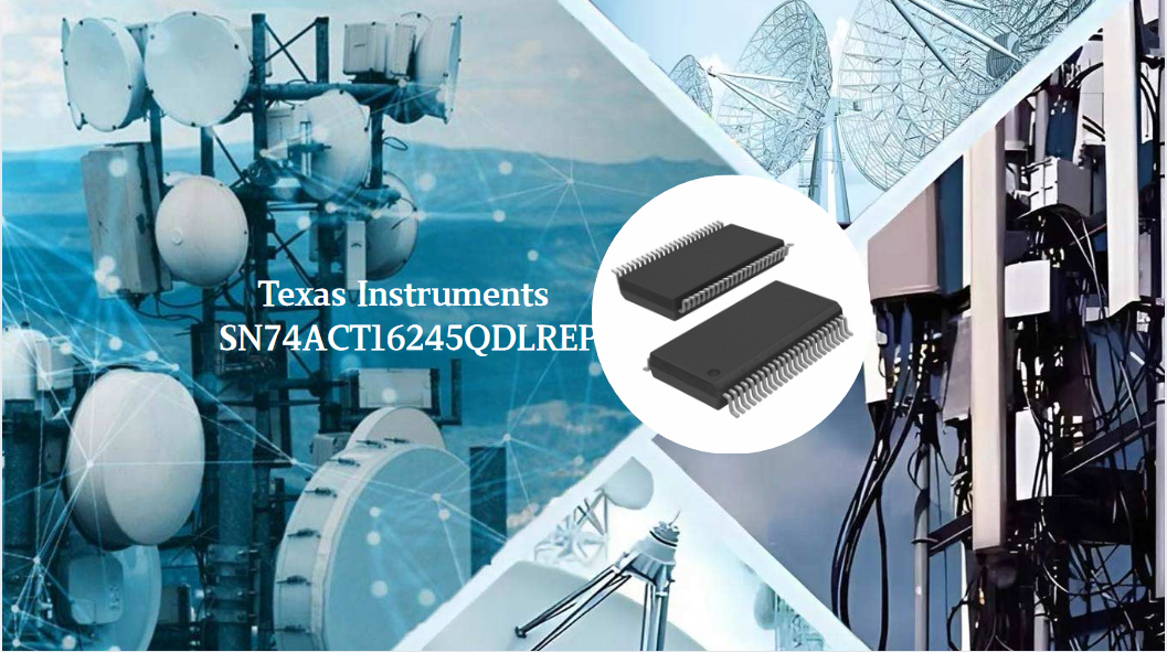
A 16-bit Bus Transceiver: Why Choose the Texas Instruments SN74ACT16245QDLREP?
The Texas Instruments SN74ACT16245QDLREP is a high-performance 16-bit bus transceiver. Designed for harsh industrial and automotive environments, it operates reliably from -40°C to +125°C. With its dual 8-bit non-inverting 3-state architecture, it enables efficient bidirectional data transfer. It of...
-
2025 / 06 / 04
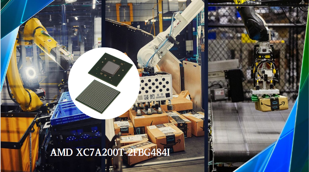
XC7A200T-2FBG484I by AMD FPGAs: A Comprehensive Guide
The AMD XC7A200T - 2FBG484I is a high - performance FPGA from the Artix - 7 series. It features 215,360 logic cells and 740 DSP slices, enabling complex logic and signal processing tasks. With a 2.9 Tb/s I/O bandwidth and support for interfaces like PCIe, it ensures fast data transfer. Using 28 - nm...
-
2025 / 05 / 30
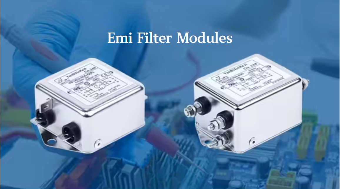
The Importance of Emi Filter Modules in Electronics
Emi filter modules are designed to suppress and filter out unwanted electromagnetic interference that can arise from various sources such as electrical appliances, motors, and radio frequency signals. By incorporating Emi filter modules into electronic devices, manufacturers can ensure that their pr...

2000+
Daily average RFQ Volume

30,000,000
Standard Product Unit

2800+
Worldwide Manufacturers

15,000 m2
In-stock Warehouse
 Wishlist (0 Items)