

- RFQ
- BOM
-
Contact Us
Tel: +86-0755-83501315
Email: sales@sic-components.com


- Chinese
- English
- French
- German
- Portuguese
- Spanish
- Russian
- Japanese
- Korean
- Arabic
- Irish
- Greek
- Turkish
- Italian
- Danish
- Romanian
- Indonesian
- Czech
- Afrikaans
- Swedish
- Polish
- Basque
- Catalan
- Esperanto
- Hindi
- Lao
- Albanian
- Amharic
- Armenian
- Azerbaijani
- Belarusian
- Bengali
- Bosnian
- Bulgarian
- Cebuano
- Chichewa
- Corsican
- Croatian
- Dutch
- Estonian
- Filipino
- Finnish
- Frisian
- Galician
- Georgian
- Gujarati
- Haitian
- Hausa
- Hawaiian
- Hebrew
- Hmong
- Hungarian
- Icelandic
- Igbo
- Javanese
- Kannada
- Kazakh
- Khmer
- Kurdish
- Kyrgyz
- Latin
- Latvian
- Lithuanian
- Luxembou..
- Macedonian
- Malagasy
- Malay
- Malayalam
- Maltese
- Maori
- Marathi
- Mongolian
- Burmese
- Nepali
- Norwegian
- Pashto
- Persian
- Punjabi
- Serbian
- Sesotho
- Sinhala
- Slovak
- Slovenian
- Somali
- Samoan
- Scots Gaelic
- Shona
- Sindhi
- Sundanese
- Swahili
- Tajik
- Tamil
- Telugu
- Thai
- Ukrainian
- Urdu
- Uzbek
- Vietnamese
- Welsh
- Xhosa
- Yiddish
- Yoruba
- Zulu
- Kinyarwanda
- Tatar
- Oriya
- Turkmen
- Uyghur
Counter Chip
I. Introduction
In today's digital age, electronic devices have permeated every aspect of our lives. From consumer electronics such as smartphones and laptops to large - scale equipment like communication base stations and servers, counter integrated circuits (ICs) play a crucial role. In the field of communication, counter ICs are used to measure the frequency and period of signals, ensuring accurate signal transmission and processing. In computer systems, they are involved in the management and control of clock signals, guaranteeing the synchronized operation of various components. In consumer electronics, such as smartwatches and electronic scales, counter ICs enable functions like time measurement and data counting.
This article aims to provide a comprehensive and in - depth introduction to counter ICs, covering their definitions, types, working principles, application scenarios, and market conditions. The goal is to help readers gain a systematic and clear understanding of counter ICs.
II. Basic Concepts of Counter ICs
Definition and Function
A counter IC, simply put, is an integrated circuit specifically designed to count input signals, commonly clock pulses. It can accurately record the number of input signals, and through the processing and analysis of these count results, a variety of functions can be achieved. For example, in terms of recording the number of events, counter ICs can be used to count the number of products on a production line or the number of vehicles passing through a traffic intersection. In time measurement, by counting stable clock pulses, counter ICs can achieve high - precision time measurement, which is commonly seen in devices like digital clocks and timers. When it comes to frequency measurement, counter ICs can count the number of cycles of an input signal within a certain time period, thereby calculating the signal's frequency. This application is widespread in frequency counters and signal frequency monitoring in communication systems.
Structural Composition
The main components of a counter IC include flip - flops, registers, and logic gates. Flip - flops are one of the core components of counter ICs. They have the ability to store binary data and are used to store the current count value. When an input signal is received, the flip - flops change their stored state according to specific logical rules, thus updating the count value. For instance, a D flip - flop stores the input data D into the flip - flop when triggered by a clock signal. A JK flip - flop, on the other hand, can perform various operations such as set, reset, hold, and toggle according to the input signals at the J and K terminals.
Registers are used to temporarily store the count values of the counter, facilitating subsequent processing and output. They can output the count values in parallel or serial mode for use by other circuits. Logic gates play a crucial role in controlling the counting operations of counter ICs. They perform logical operations based on input signals and the states of flip - flops, determining the counting direction (up or down) of the counter, whether to perform preset operations, and when to reset. For example, basic logic gates such as AND gates, OR gates, and NOT gates can be combined into complex control circuits to achieve precise control of the counter.
III. Types of Counter ICs
Classification by Working Mode
Synchronous Counters
The working principle of synchronous counters is that all flip - flops change their states synchronously under the control of the same clock signal. That is, when the active edge (rising or falling edge) of the clock signal arrives, all flip - flops update their states simultaneously according to the input signals and the current states. This working mode endows synchronous counters with the remarkable characteristics of high counting speed and accuracy.
Since all flip - flops in a synchronous counter work synchronously, there is no cumulative delay in signal transmission. Therefore, it can operate stably at a relatively high clock frequency, making it highly suitable for high - speed counting scenarios. In the field of digital signal processing, synchronous counters can be used to count high - speed pulse signals, providing accurate count information for signal processing algorithms. In high - frequency counters, synchronous counters can quickly and accurately measure the frequency of high - frequency signals, meeting the requirements of high - precision measurement.
Asynchronous Counters
The working principle of asynchronous counters differs from that of synchronous counters. In an asynchronous counter, the state changes of flip - flops do not occur synchronously but are transmitted sequentially. Usually, the first flip - flop is connected to an external clock signal, and the subsequent flip - flops are triggered by the state output (Q or Q') of the previous flip - flop. This working mode makes asynchronous counters relatively simple in hardware implementation, requiring fewer logic gates, thus reducing hardware costs.
However, asynchronous counters also have some limitations. Due to the sequential transmission of flip - flop state changes, cumulative delays occur during signal transmission, resulting in slower operation. Additionally, during the counting process, asynchronous counters may experience brief unstable states, affecting counting accuracy. Nevertheless, asynchronous counters still have advantages in some low - speed application scenarios, such as low - speed timers and simple event counters. In these scenarios, the requirement for counting speed is not high, while hardware cost and circuit simplicity are more important.
Classification by Digital Coding Method
Binary Counters
Binary counters are one of the most basic types of counters, representing count values in binary form. In a binary counter, each flip - flop represents a binary bit. As clock pulses are input, the counter counts from 0 according to binary rules. For example, a 4 - bit binary counter can count from 0000 to 1111, that is, from 0 to 15.
Binary counters are widely used in counting operations of general digital circuits. Their counting rules are simple and easy to implement and understand, and they are highly compatible with the binary data processing method inside computers. Therefore, they play a fundamental role in digital systems.
Decimal Counters
Decimal counters are characterized by using binary coding to achieve a counting cycle from 0 to 9. They are usually designed based on the structure of synchronous counters, and through specific logic circuits, binary numbers are converted into decimal representations. For example, the common BCD (Binary - Coded Decimal) code is a coding method that uses 4 - bit binary numbers to represent 1 - digit decimal numbers.
Decimal counters are widely used in devices for displaying numbers, such as digital clocks and counter displays. In these devices, numbers need to be displayed in decimal form for easy reading and understanding by people. Decimal counters can directly output BCD codes, which can be easily combined with display devices like seven - segment displays to achieve digital display functions.
Arbitrary N - base Counters
Arbitrary N - base counters are a more flexible type of counter. They achieve counting in a specific base through feedback logic. That is, when the count value of the counter reaches N - 1, a feedback signal is generated, resetting the counter and starting a new counting cycle. This design principle enables arbitrary N - base counters to meet various special counting requirements.
In specific industrial control scenarios, there may be a need to control the number of cycles of a certain production process. In such cases, arbitrary N - base counters can be designed and applied according to the specific number of cycles required. In customized counting requirements, such as in some experimental equipment or special counting systems, arbitrary N - base counters can provide flexible counting solutions.
Classification by Counting Increase/Decrease Trend
Up Counters
The working mode of up counters is that the count value increases by 1 with each incoming clock pulse. They are widely used in scenarios such as event counting and pulse counting. On a production line, up counters can be used to count the number of products. Each time a product passes through the detection point, the counter increments by 1, thereby recording the real - time production quantity. In pulse counting, up counters can count the input pulse signals, which is used to measure the number or frequency of pulses.
Down Counters
The working principle of down counters is the opposite of that of up counters. The count value decreases by 1 with each incoming clock pulse. They play an important role in applications such as countdowns and remaining quantity counting. In a countdown timer, for example, in the countdown equipment for some competitions, the down counter starts from a set initial value. As clock pulses are input, the count value gradually decreases until it reaches 0, realizing the countdown function. In remaining quantity counting, down counters can be used to record changes in inventory quantity. Each time a product is shipped out, the counter decrements by 1, reflecting the real - time remaining inventory quantity.
Synchronous Counters VS. Asynchronous Counters
Synchronous counters and asynchronous counters are widely used in digital circuits, and there are many differences between the two, as follows:
Triggering Method: In a synchronous counter, all flip - flops are driven by the same clock signal. Each flip - flop receives the clock pulse and updates its state at the same time. In an asynchronous counter, only the lowest - order flip - flop is controlled by the input clock signal. The other higher - order flip - flops rely on the output signals of adjacent lower - order flip - flops as clock signals to trigger state transitions, so the state updates of each flip - flop are not synchronized.
Counting Speed: Since all flip - flops in a synchronous counter act simultaneously without the problem of cumulative sequential delays, it has a fast counting speed and can quickly respond to clock signals to complete counting operations. In an asynchronous counter, because the flip - flops are triggered sequentially, there is a delay in signal transmission. As the number of bits in the counter increases, the cumulative delay becomes significant, resulting in a relatively slow counting speed.
Circuit Structure and Complexity: Synchronous counters require the design of specialized logic circuits to ensure that all flip - flops work in tandem under the same clock. They usually use a large number of logic gates, resulting in a complex circuit structure, high design difficulty, and relatively high cost. Asynchronous counters have a relatively simple structure, mainly composed of flip - flops and a small number of logic gates. Without the need for complex synchronous control logic, they are less difficult to design and implement, and the cost is also relatively low.
Reliability: Synchronous counters have a stable counting process, are less affected by external interference, and are not prone to counting errors, ensuring the accuracy and stability of counting. When an asynchronous counter is counting, due to the sequential triggering delay, it may experience brief unstable states. During high - speed counting, it is vulnerable to interference, leading to counting errors, and may also generate glitches, which affect its reliability.
Flexibility of Counting Sequence: Synchronous counters can achieve any counting sequence, such as circular counting, skip - step counting, and other special counting requirements, by designing complex logic control circuits and changing the clock sequence. Asynchronous counters generally can only count in fixed sequences, such as the upward (UP) or downward (DOWN) modes, and the counting sequence is relatively limited.
Delay Characteristics: Synchronous counters do not have the problem of cumulative propagation delays between flip - flops, and the state updates of all flip - flops are synchronized with the clock signal. In asynchronous counters, there is a significant propagation delay from the lowest - order flip - flop to the highest - order flip - flop, and the delay time increases as the number of bits in the counter increases.
IV. Working Principles of Counter ICs
Counting Mechanism Based on Flip - Flops
Flip - flops play a core role in the storage and state transition of counter ICs. They can change their stored binary states according to changes in input signals, thereby updating the count value. Different types of flip - flops have different applications and characteristics in counters.
The D flip - flop is a simple and commonly used type of flip - flop. It stores the input data D into the flip - flop when triggered by a clock signal. In a counter, the D flip - flop can be used to store the current count value and update its state according to the clock signal and other control signals. For example, in a simple up counter, the input data of the D flip - flop can be the result of adding 1 to the current count value. When the clock signal arrives, the D flip - flop stores the new count value, realizing the counting function.
The JK flip - flop has more functions. It can perform various operations such as set, reset, hold, and toggle according to the input signals at the J and K terminals. In a counter, by reasonably setting the signals at the J and K terminals, the JK flip - flop can realize up - counting, down - counting, and other complex counting logics. For example, when J = 1 and K = 0, the JK flip - flop performs a set operation when triggered by a clock signal; when J = 0 and K = 1, it performs a reset operation; when J = K = 1, it performs a toggle operation, thus realizing the counting function.
Role of Clock Signals
Clock signals are crucial for driving the counting operations of counters. They provide a unified time reference for the counter, controlling the timing of flip - flop state transitions. In a synchronous counter, all flip - flops rely on the same clock signal. When the active edge (rising or falling edge) of the clock signal arrives, the flip - flops update their states simultaneously, ensuring the synchronous operation of the counter.
In an asynchronous counter, although the first flip - flop is connected to an external clock signal, the clock inputs of subsequent flip - flops are provided by the state output of the previous flip - flop. The frequency and stability of the clock signal have a significant impact on the performance of the counter. If the frequency of the clock signal is too high, the flip - flops may not be able to respond in time, resulting in counting errors. If the clock signal is unstable, the counting results of the counter will be deviated.
Realization of the Counting Process
Taking a binary counter as an example, we will explain in detail the changes in flip - flop states and the update of the count value during the counting process. Suppose we have a 4 - bit binary up counter composed of 4 D flip - flops, representing the 4 bits of a binary number.
When the initial state of the counter is 0000, with the input of clock pulses, the least significant bit (LSB) flip - flop changes its state at the rising edge of each clock pulse. When the LSB changes from 0 to 1, the count value becomes 0001. When the LSB changes from 1 to 0 again, a carry is generated to the next - higher bit, causing the next - higher - bit flip - flop to change its state, and the count value becomes 0010. By analogy, as more clock pulses are input, the counter counts according to binary rules until the count value reaches 1111.
In this process, the principle of carry is that when the state of a certain flip - flop changes from 1 to 0, a carry signal is output to the next - higher bit, causing the state of the next - higher - bit flip - flop to change. The principle of borrow is similar. In a down counter, when the state of a certain flip - flop changes from 0 to 1, a borrow signal is generated to the next - higher bit, causing the state of the next - higher - bit flip - flop to change. Different base counters perform corresponding logical processing for carry and borrow according to their base characteristics.
V. Application Fields of Counter ICs
Frequency Measurement and Control
In frequency counters, counter ICs are the core components for frequency measurement. They count the number of cycles of the input signal within a certain time period and then calculate the frequency of the signal based on the count result and the time interval. For example, in a simple frequency measurement system, if the counter IC counts 1000 cycles of the input signal within 1 second, the frequency of the input signal is 1000Hz.
In communication systems, accurate measurement and control of signal frequency are of great importance. Counter ICs can be used to monitor and adjust the frequency of communication signals, ensuring the accuracy and stability of signal transmission. In wireless communication, by precisely measuring and controlling the frequency of radio - frequency signals, accurate modulation and demodulation of signals can be achieved, improving communication quality.
Time Measurement and Timing
Counter ICs play a key role in devices such as digital clocks and timers, enabling precise time measurement and display. In a digital clock, the counter IC counts the stable clock pulses generated by the crystal oscillator and converts the count results into time units such as seconds, minutes, and hours, realizing the accumulation and display of time.
In industrial control, counter ICs can be used to control and monitor the time of the production process. For example, on an automated production line, the counter IC can control the duration of a certain processing step, ensuring the accuracy and consistency of the production process. Through precise time measurement and control, production efficiency can be improved, and production errors can be reduced.
Event Counting and Statistics
On the production line, counter ICs can be used to count the number of products. By installing sensors, when a product passes through the detection point, the sensor generates a signal, and the counter IC counts these signals, thereby recording the real - time production quantity of products. This is very important for production management and quality control, as it helps enterprises to timely understand the production progress and adjust production plans.
In traffic flow monitoring, counter ICs can be used to count the number of vehicles passing through. By installing devices such as induction coils or cameras on the road, when a vehicle passes through, the device generates a signal, and the counter IC counts these signals, thus counting the traffic flow. This is of great significance for traffic management and planning, as it can help optimize the setting of traffic lights and alleviate traffic congestion.
In scientific research and experiments, counter ICs can be used to record the number of occurrences of specific events. For example, in particle physics experiments, counter ICs can be used to record the number of particle collisions, providing data support for scientific research.
Analog - to - Digital Conversion and Signal Processing
In some ADC (Analog - to - Digital Converter) circuits, counter ICs can assist in realizing quantization and encoding functions. In a successive - approximation ADC, the counter IC can cooperate with a comparator and a DAC (Digital - to - Analog Converter) to gradually approximate the quantized value of the input analog signal. The counter IC starts from an initial value and adjusts the count value according to the output result of the comparator until the quantized value closest to the input analog signal is found, and then converts this quantized value into a digital signal for output.
In digital signal processing, counter ICs can count and process signals to extract useful information. For example, when processing audio signals, the counter IC can be used to calculate the number of samples of the audio signal, thereby realizing the digital processing of the audio signal. Through the counting and analysis of signals, operations such as audio signal filtering and noise reduction can be performed to improve audio quality.
Frequency Division Circuits and Clock Management
In frequency division circuits, counter ICs can divide the input clock signal to generate clock signals of different frequencies. By setting the counting mode and count value of the counter, different frequency division ratios can be achieved. For example, a 4 - bit binary counter can achieve a frequency division ratio of 1/16, that is, reducing the frequency of the input clock signal to 1/16 of the original.
In complex electronic systems, the management and distribution of clock signals are very important. Counter ICs can be used to generate multiple clock signals of different frequencies, providing appropriate clock references for various components in the system to ensure the synchronized operation of all components. In a computer system, counter ICs can generate clock signals of different frequencies required by components such as the CPU, memory, and peripherals, ensuring the stable operation of the system.
VI. Advantages and Limitations of Using Counter ICs
Advantages
Functional Integration
Counter ICs integrate multiple components required for counting, such as flip - flops, registers, and logic gates, into a single chip. This greatly reduces the area of the circuit board and the number of components. It not only simplifies the design complexity of the circuit board but also improves the reliability and stability of the system. Since the number of components is reduced, the number of connection points in the circuit is also reduced, thereby reducing the probability of failures.
No Programming Required
Compared with counting solutions based on microcontrollers, counter ICs usually do not require programming. Simply connect the counter IC to the circuit according to its pin definitions and usage instructions and set the corresponding control signals to achieve the counting function. This greatly reduces the development difficulty and cost, allowing engineers to apply counter ICs to projects more quickly.
Low - power Design
Many counter ICs adopt low - power design techniques, which can reduce power consumption while ensuring performance. This makes counter ICs highly suitable for battery - powered devices, such as smartwatches and wireless sensors. The low - power design not only extends the battery life of the device but also reduces heat dissipation problems and improves the stability of the device.
High - speed Performance
Synchronous counter ICs can accurately count under high - frequency clock signals, meeting the requirements of high - speed digital systems. In some application scenarios with high requirements for counting speed, such as high - speed data acquisition systems and high - frequency signal processing circuits, synchronous counter ICs can quickly and accurately count input signals, providing precise count information for the system.
Limitations
Limited Counting Range
Due to the limitations of the internal structure of the chip, the counting range of counter ICs is limited. For some applications that require a large counting range, it may be necessary to cascade multiple counter ICs. For example, the maximum counting range of a 4 - bit binary counter is 0 to 15. If a larger counting range is required, multiple 4 - bit counter ICs need to be cascaded,which increases the complexity and cost of the circuit.
Clock Frequency Limitation
Each counter IC has a limit on its maximum operating clock frequency. If the frequency of the input clock signal exceeds the maximum operating frequency of the counter IC, the counter may not work properly or may produce counting errors. When designing a circuit, it is necessary to select an appropriate clock signal frequency according to the specifications of the counter IC to ensure the normal operation of the counter.
Relatively Limited Functionality
Compared with general - purpose devices such as microcontrollers, the functionality of counter ICs is relatively limited. They mainly focus on the counting function. Although some counter ICs have additional functions such as presetting, resetting, etc., their flexibility and expandability are poor. In some applications that require complex data processing and control functions, counter ICs may not be able to meet the requirements and need to be used in combination with other devices.
VII. Classification Factors and Selection Methods of IC Counters
Classification Consideration Factors
Working Mode (Synchronous/Asynchronous)
Synchronous counters are suitable for high - speed counting scenarios, capable of accurate counting at high - frequency clocks, but with relatively high hardware costs. Asynchronous counters are suitable for low - speed application scenarios, with low hardware costs, but they are slower in operation and have cumulative delay problems. When selecting, it is necessary to decide whether to use a synchronous or asynchronous counter according to the counting speed requirements of the application.
Digital Coding Method (Binary/Decimal/Other Bases)
Binary counters are the most basic counting method and are widely used. Decimal counters are suitable for occasions where numbers need to be displayed in decimal form. Arbitrary N - base counters can be customized according to special counting requirements. Select the appropriate digital coding method according to specific application requirements.
Counting Increase/Decrease Trend (Up/Down)
If the application requires cumulative counting of events, such as counting the number of products or pulses, an up counter can be selected. If it is necessary to perform operations such as countdown or remaining quantity counting, a down counter should be selected.
Counting Range
Select a counter IC with an appropriate counting range according to the maximum value that needs to be counted in the actual application. If the counting range is insufficient, it may lead to inaccurate counting results or failure to meet application requirements.
Speed Requirements
Select a counter IC that can operate stably at the corresponding frequency according to the counting speed requirements of the application. If high - speed counting is required, a synchronous counter or a counter IC with a high operating frequency should be selected.
Selection Methods
Determine the Counting Range and Working Frequency According to Application Requirements
Before selecting a counter IC, it is necessary to clearly define the specific requirements of the application, and determine the maximum value that needs to be counted and the working frequency. For example, in a high - frequency communication signal counting scenario, a counter IC that can work at a frequency of hundreds of megahertz or even higher may be required.
Consider Counting Mode (Up, Down, or Reversible) and Digital Coding Requirements
Judge the appropriate counting mode according to the actual counting task logic. If it is used to count the cumulative number of products on the production line, an up counter is the inevitable choice. For scenarios that require countdown control, such as rocket launch countdown devices, a down counter can accurately meet the demand. For complex systems that require both forward and reverse counting, a reversible counter can flexibly switch the counting direction. For example, in the pulse counting control of a motor's forward and reverse rotation, a reversible counter can reflect the number of rotations and the direction of the motor in real - time.
In terms of digital coding, if the counting result is directly used for digital display, a counter with decimal coding is more suitable. Devices like common electronic scales and price calculators can directly present numbers by outputting BCD codes and cooperating with display driver chips. If the counting data needs to be connected to a computer system for binary arithmetic processing, a binary counter can reduce the data conversion process and improve efficiency, which is widely used in scenarios such as counting clock cycles and memory addresses inside computers. For some industrial automation devices with special counting cycle requirements, such as the cycle processing times of specific workpieces, arbitrary N - base counters can be customized to meet personalized needs.
Pay Attention to Interface Types and Compatibility
The interface type determines the connection method and data transmission efficiency between the counter IC and other circuit components. Parallel interfaces have the advantage of fast data transmission speed and are suitable for scenarios with high real - time data requirements. For example, in a high - speed data acquisition system, the counter IC can quickly transmit the count value to the data processing chip through a parallel interface. Serial interfaces are characterized by low pin resource occupation and are suitable for long - distance transmission or circuit designs with limited pin resources. For example, in the counting data transmission of some distributed sensor nodes, using a serial interface can simplify the wiring and reduce costs.
At the same time, it is necessary to ensure the compatibility of the counter IC with other chips in the system (such as microcontrollers, memories, operational amplifiers, etc.). This includes electrical characteristic compatibility, such as voltage level matching. If the high - level output of the counter IC is 3.3V, but the high - level input requirement of the subsequent microcontroller is 5V, a level conversion circuit is required for adaptation. Timing compatibility is also crucial. It is necessary to ensure that the timing of the count output and control signals of the counter IC matches the operation timing of other chips to avoid data transmission errors or logical confusion and ensure the stable operation of the entire system.
Evaluate the Necessity of Additional Functions (Preset, Reset, Enable, etc.) for the Application
The preset function plays an important role in many scenarios. In applications that require counting from a specific value, such as setting the number of cycles for laboratory experiments, researchers can use the preset function to set the initial value of the counter to the required number of cycles. As each experiment is completed and triggers the count, the progress of the experiment can be monitored intuitively. The reset function is the key to system initialization and fault recovery. When an electronic device starts, the reset signal of the counter IC can clear the count value and return it to the initial state. When abnormal counting occurs in the system, manually or automatically triggering the reset can restore the normal operation of the counter and ensure system accuracy.
The enable function gives the counter flexible control capabilities. In some intermittent counting applications, such as the signal counting of periodic detection equipment, the enable signal can be used to control the counter to start counting during the detection cycle and pause at other times, reducing power consumption and avoiding invalid counting. In addition, some counter ICs also have additional functions such as carry output and borrow output. These functions can provide more state information for the system in scenarios such as cascading multiple counters and complex logic control, helping to achieve more precise control and data processing.
VIII. Definition and Standards of High - Quality Counter ICs
High - precision Counting
High - quality counter ICs must be able to achieve high - precision counting under various complex working conditions. Whether facing extreme temperature environments (such as extremely cold at - 40°C or extremely hot at 125°C in industrial environments), or when the power supply voltage fluctuates within a certain range (such as ±10% of the rated voltage), or in places with strong electromagnetic interference (such as near substations and communication base stations), the counting error can be controlled within a very small range. This relies on the use of high - precision manufacturing processes inside the chip to ensure the precise and stable flip - flop threshold, optimized logic circuit design to reduce distortion and delay during signal transmission, and advanced anti - interference technologies such as electromagnetic shielding design and integrated filter circuits to ensure the accuracy of counting results and provide reliable support for high - precision measurement and control applications.
High - speed Performance
The ability to operate stably under high - frequency clock signals is an important feature of high - quality counter ICs. With the development of electronic technology towards high - speed, in cutting - edge fields such as high - speed data acquisition, high - frequency communication, and high - speed signal processing, counter ICs need to meet clock frequency requirements of hundreds of megahertz or even several gigahertz. To achieve this performance, the chip uses advanced semiconductor materials and manufacturing processes, such as FinFET technology, to reduce the gate delay of transistors; optimizes the circuit layout to shorten the signal transmission path and reduce signal transmission delay; at the same time, conducts high - speed design of the internal logic circuit, using techniques such as pipelining and parallel processing architectures to ensure that the flip - flops can respond quickly under high - frequency clock drive, and the counter state can be updated accurately, without counting errors, missed or extra pulse counting, meeting the stringent requirements of high - speed systems for real - time counting.
Low - power Consumption
In today's era when energy efficiency is increasingly valued, high - quality counter ICs pay attention to low - power design while ensuring performance. By adopting low - power semiconductor process nodes, such as advanced 7nm and 5nm processes, the static power consumption of transistors is reduced; power management technologies such as dynamic voltage and frequency adjustment (DVFS) are used to dynamically adjust the supply voltage and clock frequency according to the workload of the counter, reducing power consumption during light loads; the circuit architecture is optimized to reduce redundant logic gates and unnecessary signal transitions, reducing dynamic power consumption. For battery - powered devices such as portable electronic devices and IoT sensor nodes, low - power counter ICs can significantly extend the device's battery life. In applications such as large - scale data centers and server clusters, the use of a large number of low - power counter ICs can reduce overall energy consumption and save operating costs, in line with the development trend of green energy conservation.
Good Stability
Excellent stability is a key characteristic of high - quality counter ICs. They can maintain normal operation under harsh environmental conditions and effectively resist the influence of factors such as voltage fluctuations, temperature changes, and electromagnetic interference. In terms of voltage fluctuations, the built - in power supply voltage regulation module and power monitoring circuit can automatically adjust the input voltage to ensure the stable operation of the internal circuits of the chip. For temperature changes, high - temperature and low - temperature resistant materials and packaging processes, as well as thermal management technologies such as heat sink design and thermal conductive adhesive filling, are used to ensure stable chip performance within a wide temperature range. In the face of electromagnetic interference, through optimized PCB layout, metal shielding cover packaging, and signal filtering technology, the electromagnetic interference resistance of the chip is enhanced, avoiding the interference of external electromagnetic signals on the counting process, ensuring that the counter IC can operate continuously and stably in complex and changeable environments, and improving the reliability of the entire electronic system.
Rich Functions
High - quality counter ICs not only have basic counting functions but also integrate rich additional functions to meet diverse application needs. In addition to common functions such as presetting, resetting, and enabling, they may also have functions such as multiple counting mode switching, such as continuous counting, single - shot counting, and cyclic counting, which are suitable for different counting task scenarios; have programmable frequency division ratio setting functions, which can flexibly adjust the output clock frequency according to actual needs; some counter ICs also integrate data latching functions, which can lock the count value at a specific moment, facilitating data reading and processing; some even have error detection and correction functions, which can real - time monitor abnormal situations during the counting process and automatically correct them, improving counting accuracy and system reliability. The rich functions make counter ICs more flexible and adaptable in complex electronic system design, reducing the use of external auxiliary circuits and simplifying the system architecture.
High Reliability
Reliability is an important indicator for measuring high - quality counter ICs. Through strict design verification and testing processes, including function testing, performance testing, environmental testing (high temperature, low temperature, humidity, vibration, etc.), and aging testing, it is ensured that the chip can operate stably under various working conditions. During the production process, strict quality control standards are followed, and advanced manufacturing processes and automated production equipment are used to reduce quality problems caused by human factors. At the same time, long - term technical support and product life - cycle guarantee are provided to ensure that the performance and functions of the counter IC always meet the requirements during the product use cycle. High - reliability counter ICs can effectively reduce the system failure rate, reduce maintenance costs and downtime, which is crucial for fields with extremely high reliability requirements such as aerospace, medical equipment, and industrial automation.
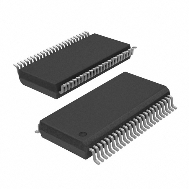
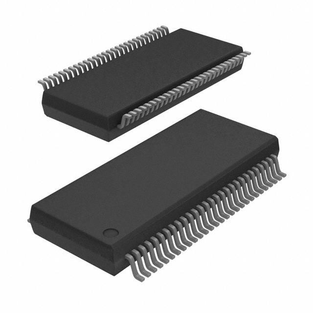
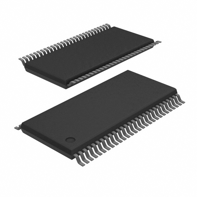
The 5 Most Popular Counter ICs on SIC
SIC offers a variety of counter ICs suitable for TTL and CMOS logic series. The Jotrin counter IC series includes 4 - bit, 8 - bit, 16 - bit, and 32 - bit binary counters. The following are the 5 most popular counter ICs on SIC.
CD4017BE https://www.sic-components.com/product/product?product_id=67253
This advanced IC belongs to the CMOS series and can serve as a 10 - stage Johnson counter (or decimal counter/divider), providing efficient functionality. Its wide application in the digital field lies in sequential counting and frequency division tasks.
CD4026BE https://www.sic-components.com/product/product?product_id=528411
Another excellent CMOS IC, the CD4026BE, is equipped with a 5 - stage Johnson decimal counter and a 7 - segment display driver. Its outstanding performance is particularly prominent in digital scenarios, as it can seamlessly count and drive the 7 - segment display to show numerical values.
SN74LS90N https://www.sic-components.com/product/product?product_id=1594895
The SN74LS90N is a TTL IC that can be used as a synchronous 4 - bit binary - decimal counter, capable of accurately counting decimal numbers from 0 to 9. Its versatility is of great significance in the digital field, where frequency division, frequency synthesis, and counting solutions are essential.
CD4060BE https://www.sic-components.com/product/product?product_id=67311
The CD4060BE is another highlight of the CMOS product line. It integrates a 14 - stage binary ripple counter and an oscillator. This CMOS chip IC with a built - in oscillator can seamlessly adapt to various digital environments, such as frequency division, timing, and clock generation.
CD4040BE https://www.sic-components.com/product/product?product_id=67285
The CD4040BE holds a unique position in the CMOS IC series. It is a 12 - stage binary ripple counter that can effectively handle up to 2^12 (4096) binary states. Its powerful performance is evident in numerous digital scenarios that require frequency division, timing, or counting.
Counter integrated circuits are the key to modern electronic systems and play an important role in many fields. Different types have their own characteristics and applicable scenarios. Although they are widely used, they also have limitations such as limited counting range. When selecting, multiple factors need to be comprehensively considered to ensure system adaptation. High - quality counter ICs need to meet the standards of high - precision, high - speed, low - power consumption, etc., to ensure the stable operation of the system.
https://www.sic-components.com/integrated-circuits-ics

Hot Products
View More-
74ALVCH16271DGGRE4 Texas Instruments
-
SN74ALVCH162836DLR Texas Instruments
-
74LCX16500GX onsemi
-
SN74ALVCHR16601G Texas Instruments
-
74ABT162501DGGRG4 Texas Instruments
-
GTLP18T612MTDX onsemi
-
SN74LVTH16501DGGR Texas Instruments
-
CVMEH22501AMDGGREP Texas Instruments
-
SN74LVTH16501DL Texas Instruments
-
SN74ALVC16834DL Texas Instruments
-
SN74ALVC162835DLR Texas Instruments
-
GTLP16617MTD Fairchild Semiconductor
Related Blogs
-
2025 / 06 / 30
Multivariate Application Analysis of Power Amplifiers in Sensor Testing
In the field of modern sensor testing, power amplifiers (PAs) serve as core components and play an indispensable role. From amplifying weak signals to simulating complex physical environments, power amplifiers provide solid guarantees for the precise testing of sensor performance through their uniqu...
-
2025 / 06 / 28
ESP32 vs STM32: Which Microcontroller Suits You Better?
In the field of embedded development, both ESP32 and STM32 are highly favored microcontrollers, each with unique features and advantages. When facing project development, how do you choose between them? This requires comprehensive consideration of multiple factors. The following detailed comparison ...
-
2025 / 06 / 26
Key Strategies to Enhance Buck Power Supply Efficiency
Improving the efficiency of Buck (step-down) switching power supplies requires a multi-dimensional approach targeting energy loss sources, including component selection, topology optimization, control strategies, and thermal management. Below are core strategies and engineering practices:...
-
2025 / 06 / 26
P-Channel MOSFET Turn-On Conditions
The turn-on conditions for a P-channel MOSFET (PMOS) are inverse to those of an N-channel MOSFET (NMOS), primarily governed by the relationship between the gate-source voltage (VGS) and the threshold voltage (Vth), along with voltage polarity. Here are the key points:A PMOS turns on when its gate vo...
-
2025 / 06 / 24
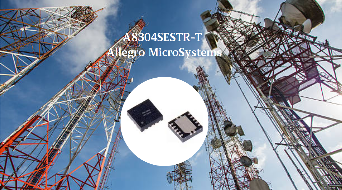
A8304SESTR-T Allegro MicroSystems-Single LNB Supply and Control Voltage Regulator
The Allegro MicroSystems A8304SESTR-T is a single-channel Low Noise Block Regulator (LNBR). It integrates a monolithic boost converter with MOSFET, current sensing, and compensation. Featuring a 704 kHz switching frequency, it uses few external components. With an I²C-compatible interface, it offers...
-
2025 / 06 / 20
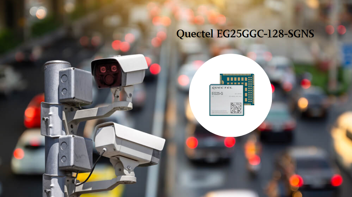
EG25GGC-128-SGNS by Quectel Wireless Solutions Co., Ltd: Features,Symbol,Footprint and Datasheet
The Quectel EG25GGC - 128 - SGNS is an LTE Cat 4 module optimized for M2M and IoT. Supporting 3GPP Rel. 11, it offers up to 150Mbps downlink and 50Mbps uplink. With global LTE/UMTS/GSM coverage, it's backward - compatible with EDGE/GPRS. Featuring multi - constellation GNSS (GPS, GLONASS, BeiDou, et...
-
2025 / 06 / 17
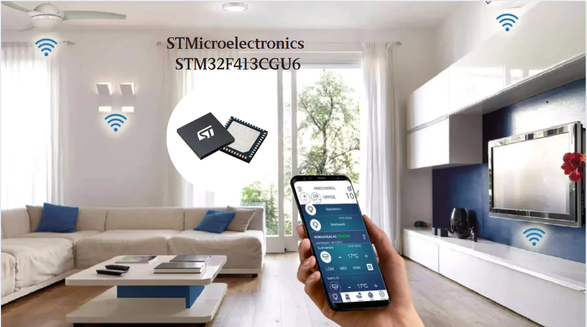
STMicroelectronics STM32F413CGU6 Microcontroller: Datasheet, Performance, Features
The STMicroelectronics STM32F413CGU6 is an Arm® Cortex®-M4 based MCU with FPU, operating at up to 100 MHz for 125 DMIPS performance. It features 1MB Flash, 320KB SRAM, and interfaces like USB OTG FS, 3 CAN, ADC, 2 DAC, and multiple serial ports. With low-power modes (Sleep, Stop, Standby), it suits ...
-
2025 / 06 / 13
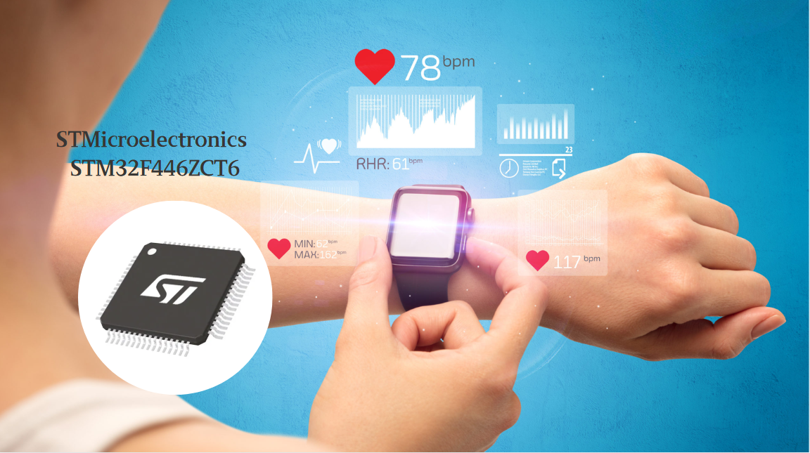
STMicroelectronics STM32F446ZCT6 -Microcontrollers: A Comprehensive Guide
The STMicroelectronics STM32F446ZCT6 is an ARM Cortex-M4-based MCU with FPU, running at up to 180 MHz. It features 256 KB Flash, 128 KB SRAM + 4 KB backup SRAM, and offers rich peripherals: USB OTG HS/FS, 2 CAN, 3 ADCs, 17 timers, and 20 communication interfaces. In LQFP144 package, industrial temp ...
-
2025 / 06 / 09
MC33887PNB NXP Semiconductors-Motor Drivers:A Comprehensive Guide
The NXP Semiconductors MC33887PNB is a 5.0 A H - bridge power IC with integrated load current feedback. It operates across a 5.0 V - 28 V voltage range, features low RDS(on) (120 mΩ typical), and supports up to 10 kHz PWM. With functions like active current limiting and fault reporting, it ensures r...
-
2025 / 06 / 07
A 16-bit Bus Transceiver: Why Choose the Texas Instruments SN74ACT16245QDLREP?
The Texas Instruments SN74ACT16245QDLREP is a high-performance 16-bit bus transceiver. Designed for harsh industrial and automotive environments, it operates reliably from -40°C to +125°C. With its dual 8-bit non-inverting 3-state architecture, it enables efficient bidirectional data transfer. It of...

2000+
Daily average RFQ Volume

30,000,000
Standard Product Unit

2800+
Worldwide Manufacturers

15,000 m2
In-stock Warehouse
 Wishlist (0 Items)