

- RFQ
- BOM
-
Contact Us
Tel: +86-0755-83501315
Email: sales@sic-components.com


- Chinese
- English
- French
- German
- Portuguese
- Spanish
- Russian
- Japanese
- Korean
- Arabic
- Irish
- Greek
- Turkish
- Italian
- Danish
- Romanian
- Indonesian
- Czech
- Afrikaans
- Swedish
- Polish
- Basque
- Catalan
- Esperanto
- Hindi
- Lao
- Albanian
- Amharic
- Armenian
- Azerbaijani
- Belarusian
- Bengali
- Bosnian
- Bulgarian
- Cebuano
- Chichewa
- Corsican
- Croatian
- Dutch
- Estonian
- Filipino
- Finnish
- Frisian
- Galician
- Georgian
- Gujarati
- Haitian
- Hausa
- Hawaiian
- Hebrew
- Hmong
- Hungarian
- Icelandic
- Igbo
- Javanese
- Kannada
- Kazakh
- Khmer
- Kurdish
- Kyrgyz
- Latin
- Latvian
- Lithuanian
- Luxembou..
- Macedonian
- Malagasy
- Malay
- Malayalam
- Maltese
- Maori
- Marathi
- Mongolian
- Burmese
- Nepali
- Norwegian
- Pashto
- Persian
- Punjabi
- Serbian
- Sesotho
- Sinhala
- Slovak
- Slovenian
- Somali
- Samoan
- Scots Gaelic
- Shona
- Sindhi
- Sundanese
- Swahili
- Tajik
- Tamil
- Telugu
- Thai
- Ukrainian
- Urdu
- Uzbek
- Vietnamese
- Welsh
- Xhosa
- Yiddish
- Yoruba
- Zulu
- Kinyarwanda
- Tatar
- Oriya
- Turkmen
- Uyghur
Buck Converters (Step-Down Converter)
I. Fundamental Definition and Core Value of Buck Converters https://www.sic-components.com/dc-dc-converters
As a core device for DC-DC power conversion, the Buck converter (step-down converter) transforms higher DC voltage into lower DC voltage via switching mode, achieving typical efficiencies of 85%-95%—far exceeding linear regulators' 50%-70%. Its technical advantages include:
High energy efficiency: Uses Pulse Width Modulation (PWM) to control duty cycle, avoiding resistive losses in linear regulators.
Size advantage: Employs inductors for energy storage instead of high-power resistors, reducing volume by 30%-50% at the same power.
Wide-range adaptability: Supports step-down from 5V to 100V input, with output voltage adjustable below 0.8V.
Buck converters have become standard in power management for smartphones, automotive electronics, and server power supplies. For example, the 15W charger of iPhone 15 uses a Buck topology with GaN switches, achieving 93% efficiency in 1/4 the size of traditional linear solutions.
II. In-Depth Working Principle: The Energy Magic of Switching Mode
1. Core Operating Cycles
The Buck converter operates based on inductor energy storage-release characteristics in two stages:
On-Time (Ton):
The switch (MOSFET) conducts, supplying input voltage Vin to the load through inductor L while storing energy, with current I_L increasing linearly:
Formula: V_L = Vin - Vout, I_L(t) = (Vin - Vout)/L × t
Off-Time (Toff):
The switch turns off, and the inductor releases energy through the freewheeling diode D, with current I_L decreasing linearly:
Formula: V_L = -Vout, I_L(t) = Vout/L × t
2. Key Component Function Matrix
Component Function Mechanism Selection Criteria
Switch Generates pulsed voltage via high-frequency on/off Rds(on) < 50mΩ, switching speed > 100ns
Freewheeling Diode Provides current path during off-state Schottky diode, reverse recovery time < 100ns
Inductor Energy storage and filtering Saturation current > 1.5× peak current, ESR < 50mΩ
Output Capacitor Smooths voltage ripple Low ESR, capacitance calculated for ripple requirements
3. Closed-Loop Control Logic
The feedback network (voltage divider resistors + error amplifier) samples output voltage in real time, compares it with the reference voltage, and adjusts PWM duty cycle D for stable output:
Formula: Vout = Vin × D, D = Vout/Vin
Typical response time < 100μs, with voltage overshoot < 5% under load transients.
III. Design Considerations and Performance Trade-offs
1. Efficiency Optimization Strategies
Synchronous rectification replacement: Replaces diodes with low-resistance MOSFETs, reducing conduction losses and improving light-load efficiency by 10% (e.g., TI LM2596 synchronous version).
Frequency selection: 1MHz high-frequency design reduces inductor size but increases switching losses; optimal frequency balances at 300kHz-1MHz.
Wide-bandgap devices: GaN switches (e.g., EPC2055) reduce switching losses by 70%, suitable for >65W fast charging.
2. Noise Suppression Solutions
LC filter optimization:
L = 10-47μH, C = 10-100μF (low ESR ceramic capacitor), cutoff frequency f_c = 1/(2π√LC) < 100kHz.
PCB layout:
Switching loop area < 2cm², input/output capacitors placed close to IC, star grounding adopted.
3. Thermal Management Design
Power loss calculation:
Ploss = Iout²×Rds(on) + Vf×Iout (diode loss) + Eswitch×f.
Heat dissipation measures:
TO-220 packages require heat sinks (thermal resistance < 10°C/W); SOT-23 packages can dissipate heat via PCB copper cladding.
IV. Typical Application Scenarios and Topology Evolution
1. Consumer Electronics
Smartphone fast charging: OPPO's 65W SuperVOOC charger uses dual Buck parallel topology, 9V/7.2A output, 94% efficiency, enabling full charge in 30 minutes with GaN switches.
Tablet PCs: iPad Pro's PD charger uses synchronous Buck with <50mV ripple at 5V/3A, meeting low-noise requirements for touch ICs.
2. Automotive Electronics
12V power systems: In-vehicle multimedia hosts use Buck converters to step down 24V batteries to 12V, supporting 3A output and AEC-Q100 compliance.
LED lighting: Automotive headlight drivers use constant-current Buck, converting 12V input to 350mA, with PWM dimming at 200Hz-10kHz.
3. Industrial and Energy Sectors
PV energy storage: 10kW energy storage converters use synchronous Buck for 48V→12V conversion, 96% efficiency, supporting parallel expansion.
Servo drives: Industrial robot joint motor drives adopt isolated Buck + flyback combined topologies for 400V→24V conversion.
V. Topology Structures and Technological Evolution
1. Traditional Buck vs. Synchronous Buck
Metric Traditional Buck (Asynchronous) Synchronous Buck (Synchronous)
Freewheeling Element Diode Low-resistance MOSFET
Efficiency (12V→5V) 88%@3A 94%@3A
Light-load Losses Higher (diode quiescent current) Lower (MOSFET zero-current turn-off)
Cost Lower (cheap diodes) Higher (requires driver circuits)
2. Integration and Intelligence Trends
Single-chip solutions: TI LM5146 integrates MOSFET and driver, 40V/5A output, size only 5mm×6mm.
Digital control: STM32G4 series MCUs enable digital PID adjustment, load transient response time < 50μs.
3D packaging: Vicor ChiP technology vertically stacks inductors and switches, achieving 1500W/in³ power density.
VI. Key Parameters and Selection Guide
1. Core Electrical Parameters
Input voltage range (Vin): Must cover actual operating voltage fluctuations (e.g., 4.5V-40V wide-range models for automotive applications).
Output current (Iout): Maintain 20% margin (e.g., select 5A rated chip for 3A load).
Switching frequency (f): High frequency (>500kHz) suits small size; low frequency (<300kHz) prioritizes efficiency.
2. Selection Process Example
Specify Vin=24V, Vout=5V, Iout=2A, ripple < 50mV.
Calculate duty cycle D=5/24≈0.21.
Select inductor L=47μH (saturation current >3A), capacitor C=47μF/10V (ESR<20mΩ).
Chip selection: TI LM2576 (3A rated, 85% efficiency) or synchronous LM2596 (92% efficiency).
VII. Design Practice and Fault Troubleshooting
1. Typical Circuit Design
Circuit Architecture
Vin(24V) → Input Capacitor(100μF) → Switch(MOSFET) → Inductor(47μH) → Output Capacitor(47μF) → Vout(5V)
Feedback Network: R1=10kΩ, R2=2.2kΩ (Voltage Division Ratio 5/2.5=2, Reference Voltage 2.5V)
2. Common Fault Handling
Low Output Voltage:
Check for value drift in feedback resistors, anomalies in the duty cycle control circuit, and inductor saturation.
Excessive Heating:
Measure Rds(on) of the switch for increase, inspect the freewheeling diode for damage, and ensure adequate heat dissipation.
High Ripple:
Increase output capacitance or parallel low ESR capacitors; optimize PCB layout to reduce loop inductance.
VIII. Future Technological Trends
1. Wide-Bandgap Semiconductor Applications
GaN Buck Converters (e.g., EPC2040): Support 1MHz switching, reducing 65W fast charger size by 40%.
SiC MOSFETs: For Buck applications above 100V, achieving 98% efficiency in industrial power supplies.
2. Digitalization and Intelligence
AI Predictive Maintenance: Analyzes current ripple to predict inductor aging with >90% accuracy.
Adaptive Control: Dynamically adjusts switching frequency based on load, automatically switching to PFM mode under light loads.
3. High-Density Integration
Heterogeneous Integration: Integrates Buck converters with MCUs and sensors in SoCs for IoT node power supplies.
Inductor-Less Buck: Replaces inductors with ceramic capacitors, reducing volume by 70% for wearable devices.
Conclusion
As a fundamental component of power electronics, the Buck converter's technological evolution centers around three core principles: efficiency, miniaturization, and intelligence. From traditional silicon MOSFETs to wide-bandgap devices, and from analog control to digital AI optimization, Buck converters have evolved beyond mere voltage regulators into intelligent nodes of the energy internet. With the maturation of GaN/SiC technologies and the proliferation of 3D packaging, Buck converters will continue to drive energy efficiency revolutions across consumer electronics, electric vehicles, and industrial automation under carbon neutrality goals, serving as a cornerstone for advancements in power electronics.
https://www.sic-components.com/dc-dc-converters

Hot Products
View More-

6AG41122KT743FC3 Siemens
-
0810541581 Anvil
-
1301940198 Molex
-
NPQM-L-G38-Q8-P10 Festo Corporation
-
SGE-225-2-4000 05000C Omron Automation and Safety
-
CE982081 Elesa USA Corporation
-
C200HE-CPU42 Omron Automation and Safety
-
88974134 Crouzet
-
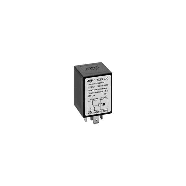
05930300 Littelfuse Inc.
-
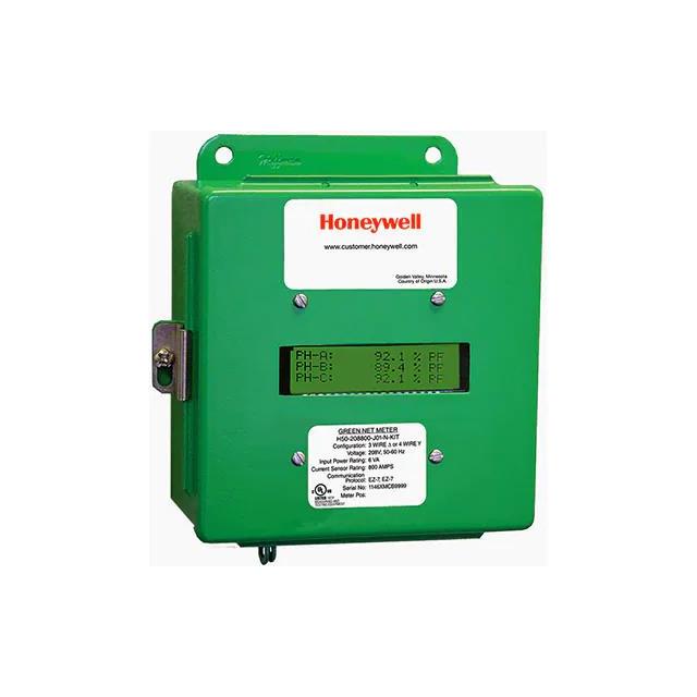
E50-600800-J03NSPKIT-NS Honeywell
-
SGE-225-0-1400 10000C-01000C Omron Automation and Safety
-

9050JCK17V20 Schneider Electric
Related Blogs
-
2025 / 07 / 09
CD4007: A Comprehensive Analysis of a Multifunctional CMOS Integrated Circuit
In the field of modern electronic technology, CMOS (Complementary Metal-Oxide-Semiconductor) integrated circuits have become core components in digital and analog circuit design due to their low power consumption, high integration, and excellent compatibility. As a classic CMOS device, the CD4007 oc...

-
2025 / 07 / 07
Understanding IC 7408: A Fundamental Component in Digital Logic Design
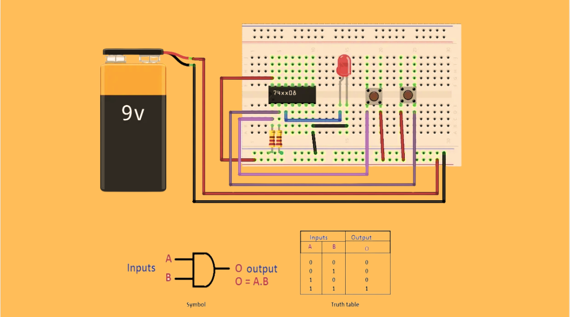
In the vast and intricate realm of digital electronics, integrated circuits (ICs) serve as the building blocks that enable the creation of complex and powerful systems. Among these, the IC 7408 holds a special place as a fundamental component in digital logic design. This article aims to provide a c...
-
2025 / 07 / 04
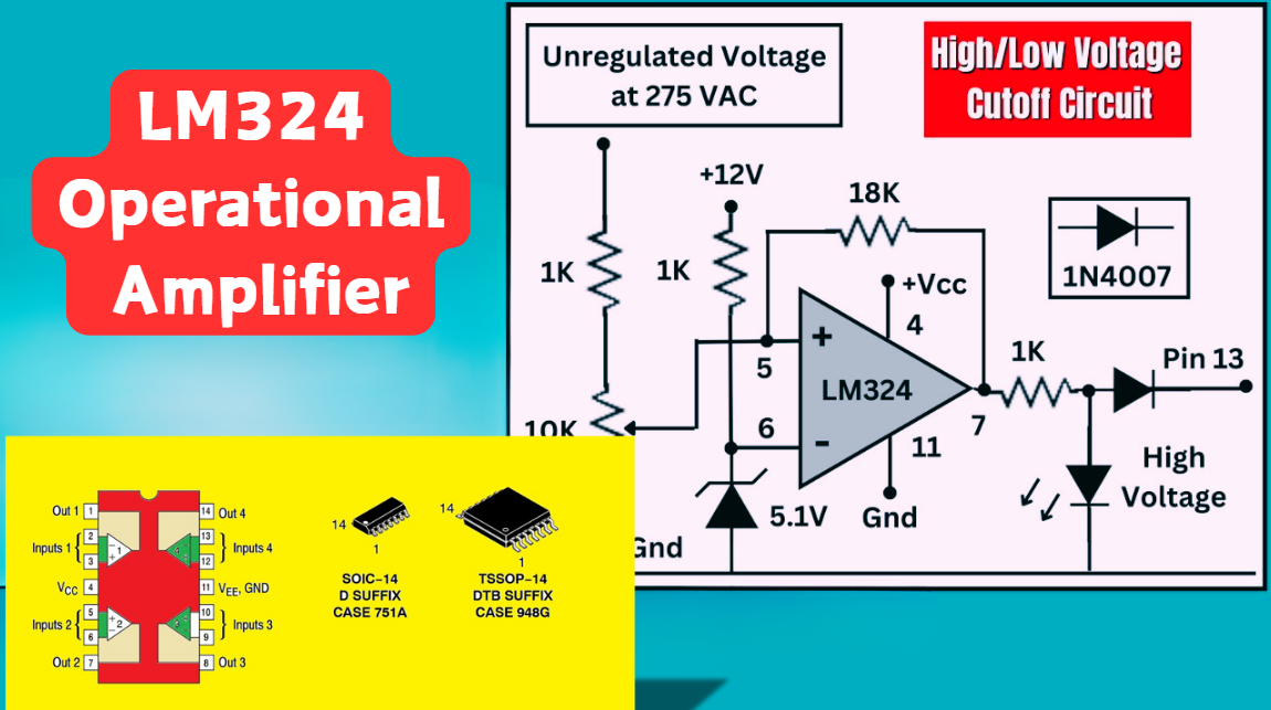
LM324 Operational Amplifier Comprehensive Guide: Pins, Applications, Packaging, and Datasheet
The LM324 is a low-cost integrated circuit featuring four independent operational amplifiers (op-amps), renowned for its wide voltage adaptability, low power consumption, and high reliability in industrial and consumer electronics. With a single-supply voltage range of 3V to 32V (or dual-supply rang...
-
2025 / 07 / 02
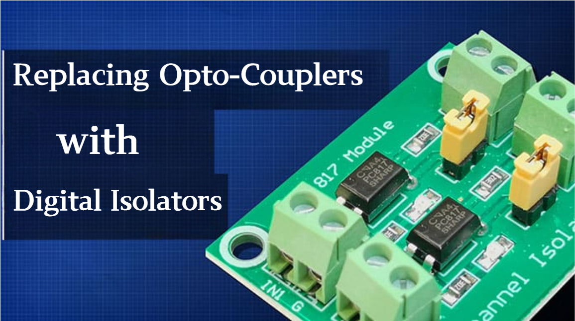
A Comprehensive Guide to Replacing Opto-Couplers with Digital Isolators: From Principles to Practice
In the ever-evolving landscape of electronic design, the transition from opto-couplers to digital isolators marks a pivotal shift in isolation technology. For decades, opto-couplers have been the cornerstone of electrical isolation in industrial control, medical devices, and power systems, relying o...
-
2025 / 06 / 30
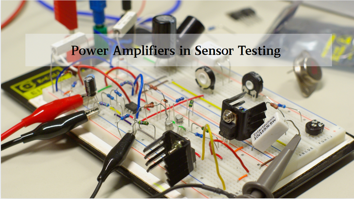
Multivariate Application Analysis of Power Amplifiers in Sensor Testing
In the field of modern sensor testing, power amplifiers (PAs) serve as core components and play an indispensable role. From amplifying weak signals to simulating complex physical environments, power amplifiers provide solid guarantees for the precise testing of sensor performance through their uniqu...
-
2025 / 06 / 28
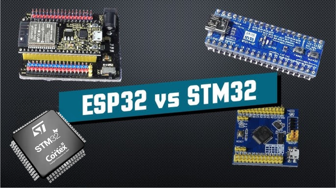
ESP32 vs STM32: Which Microcontroller Suits You Better?
In the field of embedded development, both ESP32 and STM32 are highly favored microcontrollers, each with unique features and advantages. When facing project development, how do you choose between them? This requires comprehensive consideration of multiple factors. The following detailed comparison ...
-
2025 / 06 / 26
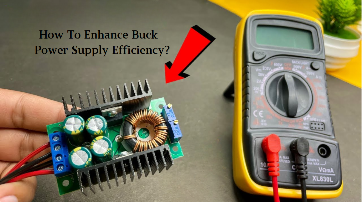
Key Strategies to Enhance Buck Power Supply Efficiency
Improving the efficiency of Buck (step-down) switching power supplies requires a multi-dimensional approach targeting energy loss sources, including component selection, topology optimization, control strategies, and thermal management. Below are core strategies and engineering practices:...
-
2025 / 06 / 26
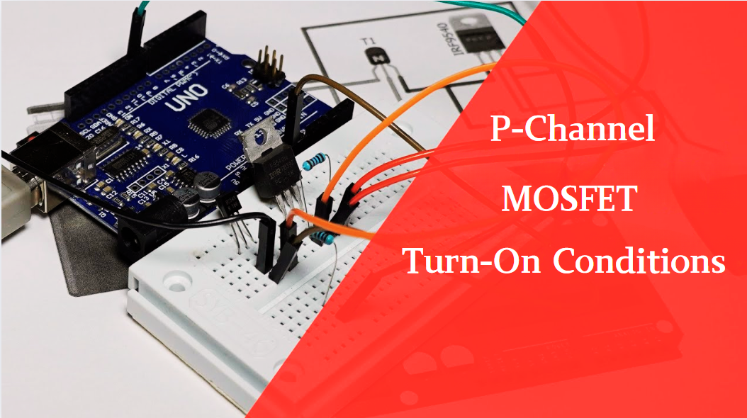
P-Channel MOSFET Turn-On Conditions
The turn-on conditions for a P-channel MOSFET (PMOS) are inverse to those of an N-channel MOSFET (NMOS), primarily governed by the relationship between the gate-source voltage (VGS) and the threshold voltage (Vth), along with voltage polarity. Here are the key points:A PMOS turns on when its gate vo...
-
2025 / 06 / 24
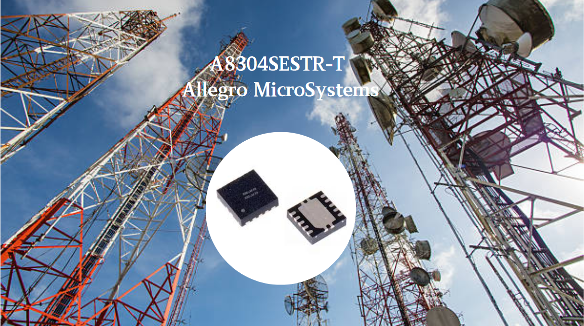
A8304SESTR-T Allegro MicroSystems-Single LNB Supply and Control Voltage Regulator
The Allegro MicroSystems A8304SESTR-T is a single-channel Low Noise Block Regulator (LNBR). It integrates a monolithic boost converter with MOSFET, current sensing, and compensation. Featuring a 704 kHz switching frequency, it uses few external components. With an I²C-compatible interface, it offers...
-
2025 / 06 / 20
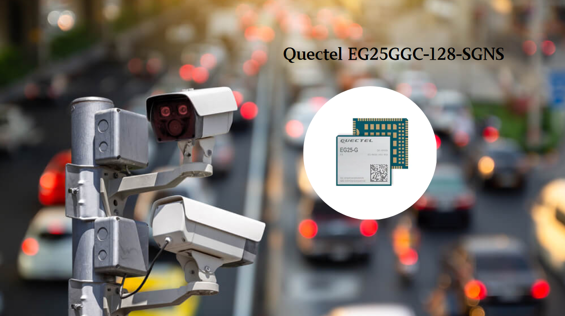
EG25GGC-128-SGNS by Quectel Wireless Solutions Co., Ltd: Features,Symbol,Footprint and Datasheet
The Quectel EG25GGC - 128 - SGNS is an LTE Cat 4 module optimized for M2M and IoT. Supporting 3GPP Rel. 11, it offers up to 150Mbps downlink and 50Mbps uplink. With global LTE/UMTS/GSM coverage, it's backward - compatible with EDGE/GPRS. Featuring multi - constellation GNSS (GPS, GLONASS, BeiDou, et...

2000+
Daily average RFQ Volume

30,000,000
Standard Product Unit

2800+
Worldwide Manufacturers

15,000 m2
In-stock Warehouse
 Wishlist (0 Items)