

- RFQ
- BOM
-
Contact Us
Tel: +86-0755-83501315
Email: sales@sic-components.com


- Chinese
- English
- French
- German
- Portuguese
- Spanish
- Russian
- Japanese
- Korean
- Arabic
- Irish
- Greek
- Turkish
- Italian
- Danish
- Romanian
- Indonesian
- Czech
- Afrikaans
- Swedish
- Polish
- Basque
- Catalan
- Esperanto
- Hindi
- Lao
- Albanian
- Amharic
- Armenian
- Azerbaijani
- Belarusian
- Bengali
- Bosnian
- Bulgarian
- Cebuano
- Chichewa
- Corsican
- Croatian
- Dutch
- Estonian
- Filipino
- Finnish
- Frisian
- Galician
- Georgian
- Gujarati
- Haitian
- Hausa
- Hawaiian
- Hebrew
- Hmong
- Hungarian
- Icelandic
- Igbo
- Javanese
- Kannada
- Kazakh
- Khmer
- Kurdish
- Kyrgyz
- Latin
- Latvian
- Lithuanian
- Luxembou..
- Macedonian
- Malagasy
- Malay
- Malayalam
- Maltese
- Maori
- Marathi
- Mongolian
- Burmese
- Nepali
- Norwegian
- Pashto
- Persian
- Punjabi
- Serbian
- Sesotho
- Sinhala
- Slovak
- Slovenian
- Somali
- Samoan
- Scots Gaelic
- Shona
- Sindhi
- Sundanese
- Swahili
- Tajik
- Tamil
- Telugu
- Thai
- Ukrainian
- Urdu
- Uzbek
- Vietnamese
- Welsh
- Xhosa
- Yiddish
- Yoruba
- Zulu
- Kinyarwanda
- Tatar
- Oriya
- Turkmen
- Uyghur
Current-Feedback Amplifiers vs. Voltage-Feedback Amplifiers
Operational amplifiers (op-amps) are the backbone of analog electronics, enabling signal amplification, filtering, and conditioning. Among the diverse op-amp architectures, Current-Feedback Amplifiers (CFAs) and Voltage-Feedback Amplifiers (VFAs) stand out as two distinct designs, each optimized for specific performance tradeoffs. This article explores their core principles, key differences, and practical applications to guide engineers in selecting the right device for their needs.
1. Core Principles: How They Work
Voltage-Feedback Amplifiers (VFAs)
VFAs are the traditional op-amp architecture, relying on voltage-driven feedback to regulate gain and stability:
Input Stage: A differential amplifier compares the voltage difference between the non-inverting (+) and inverting (-) inputs. This stage amplifies the differential voltage while rejecting common-mode signals (noise present on both inputs).
Gain Stage: The amplified differential signal passes through a high-gain voltage amplifier (typically with open-loop gains exceeding 100,000).
Feedback Mechanism: A portion of the output voltage is "fed back" to the inverting input via external resistors (e.g., Rf and Rg). This feedback minimizes the input voltage difference, stabilizing the closed-loop gain.
Key Trait: Closed-loop gain is determined by the ratio of feedback components (e.g., Gain} =1+Rf/Rg for non-inverting configurations).
Input Stage: The non-inverting input (+) connects to a unity-gain voltage buffer, providing ultra-high input impedance (similar to VFAs). The inverting input (-) acts as a current summing node, where input current (from the signal source) and feedback current (from the output via Rf are summed.
Transimpedance Amplifier: The summed current at the inverting node is converted to a voltage by an internal transimpedance amplifier (gain measured in ohms, Zt, which drives the output.
Feedback Mechanism: Feedback current, not voltage, regulates the output. The value of Rf directly influences bandwidth and gain, rather than gain alone.
Key Trait: Closed-loop gain depends on both Rf and the transimpedance gain (Gain approx Zt/Rf), making bandwidth less dependent on gain.
2. Performance Comparison
Characteristic Voltage-Feedback Amplifiers (VFAs) Current-Feedback Amplifiers (CFAs)
Gain-Bandwidth Product (GBW) Fixed for a given device; gain and bandwidth are inversely proportional (e.g., doubling gain halves bandwidth). Not fixed; bandwidth remains stable across a wide gain range (e.g., 100 MHz at gain=1 and 80 MHz at gain=10).
Slew Rate Moderate (typically 1–100 V/µs) due to internal compensation capacitors that limit speed to prevent oscillation. Exceptionally high (100 V/µs to 10 kV/µs) because they lack compensation capacitors, enabling faster response to large signals.
Stability Stability depends on gain and load capacitance. High gain improves stability, but capacitive loads (>100 pF) may cause oscillation. More stable with capacitive loads and varying feedback resistors, as stability is decoupled from gain.
Input Impedance High differential impedance (kΩ to MΩ) for both inputs, ideal for voltage-driven sources (e.g., sensors). Non-inverting input has high impedance; inverting input has low impedance (<100 Ω) due to current summing, requiring careful source matching.
Noise Performance Superior voltage noise (nV/√Hz) and linearity, critical for precision applications (e.g., medical sensors). Higher voltage noise but lower current noise, beneficial in high-speed circuits where current noise dominates (e.g., RF systems).
Gain Lineararity Excellent at low to moderate frequencies, with distortion <0.01% in audio bands. Linear at high frequencies but may degrade at extreme speeds due to transimpedance stage limitations.
3. Application Scenarios
Voltage-Feedback Amplifiers (VFAs)
VFAs excel in precision-critical, low-to-moderate speed applications:
Precision Instrumentation: Data acquisition systems, pH meters, and strain gauge amplifiers rely on VFAs’ low noise and linearity to resolve microvolt-level signals.
Audio Electronics: Hi-fi amplifiers and mixing consoles use VFAs for low distortion and flat frequency response across the 20 Hz–20 kHz audio band.
Active Filters: Low-pass, band-pass, or notch filters require VFAs’ predictable gain-bandwidth tradeoff to maintain stable cutoff frequencies.
Battery-Powered Devices: Low quiescent current (µA range) makes VFAs ideal for wearables and portable sensors.
Current-Feedback Amplifiers (CFAs)
CFAs dominate high-speed, high-slew-rate applications:
High-Frequency Communication: RF transceivers, 5G base stations, and fiber-optic links use CFAs to amplify signals up to GHz frequencies.
Video and Imaging: Broadcast equipment and oscilloscopes require CFAs’ fast slew rates to preserve sharp edges in 1080p/4K video signals.
Pulse Amplification: Radar systems and laser drivers depend on CFAs to generate narrow, high-amplitude pulses with rise times <10 ns.
Capacitive Loads: Driving coaxial cables (50–75 Ω) or piezoelectric sensors is easier with CFAs, as they tolerate capacitive loads without oscillation.
4. Design Considerations
Component Selection:
For VFAs: Match feedback resistors Rf, Rg to minimize gain error; avoid large Rf (which increases noise).
For CFAs: Use datasheet-recommended Rf values (typically 50–1000 Ω) to optimize bandwidth and stability.
Layout:
VFAs are less sensitive to parasitic capacitance but require short, matched traces for differential signals.
CFAs demand careful grounding of the inverting node to minimize stray inductance, which degrades high-frequency performance.
Cost: VFAs are cheaper and more widely available for general use; CFAs are premium components, justified only in high-speed designs.
5. Conclusion
The choice between CFAs and VFAs hinges on tradeoffs between speed, precision, and application requirements:
VFAs are the default for precision, low noise, and predictable gain in low-to-moderate speed systems.
CFAs are indispensable for high-frequency, high-slew-rate applications where bandwidth stability and fast response are critical.
By understanding these differences, engineers can leverage each architecture’s strengths to design robust analog circuits, from sensitive sensors to cutting-edge communication systems.
https://www.sic-components.com/amplifierscategory-1
https://www.ti.com/lit/slva051

Hot Products
View More-

RJHSEJ48H Amphenol ICC (Commercial Products)
-
SI-60168-F Stewart Connector
-

0826-1X1T-KH-F Bel Fuse Inc.
-
SI-60206-F Bel Fuse Inc.
-

RJE051661310 Amphenol ICC (Commercial Products)
-
RJHSEJE86 Amphenol ICC (Commercial Products)
-
RJE031660320 Amphenol ICC (Commercial Products)
-
J9P018832N85202 EDAC Inc.
-
GMX-SMT2-S-1010 Kycon, Inc.
-
SI-60090-F Stewart Connector
-
RJHSEJ489 Amphenol ICC (Commercial Products)
-
ARJM11B1-517-AB-ER2-T Abracon LLC
Related Blogs
-
2025 / 07 / 09
CD4007: A Comprehensive Analysis of a Multifunctional CMOS Integrated Circuit
In the field of modern electronic technology, CMOS (Complementary Metal-Oxide-Semiconductor) integrated circuits have become core components in digital and analog circuit design due to their low power consumption, high integration, and excellent compatibility. As a classic CMOS device, the CD4007 oc...

-
2025 / 07 / 07
Understanding IC 7408: A Fundamental Component in Digital Logic Design
In the vast and intricate realm of digital electronics, integrated circuits (ICs) serve as the building blocks that enable the creation of complex and powerful systems. Among these, the IC 7408 holds a special place as a fundamental component in digital logic design. This article aims to provide a c...
-
2025 / 07 / 04
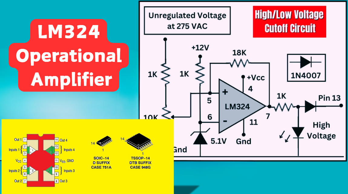
LM324 Operational Amplifier Comprehensive Guide: Pins, Applications, Packaging, and Datasheet
The LM324 is a low-cost integrated circuit featuring four independent operational amplifiers (op-amps), renowned for its wide voltage adaptability, low power consumption, and high reliability in industrial and consumer electronics. With a single-supply voltage range of 3V to 32V (or dual-supply rang...
-
2025 / 07 / 02
A Comprehensive Guide to Replacing Opto-Couplers with Digital Isolators: From Principles to Practice
In the ever-evolving landscape of electronic design, the transition from opto-couplers to digital isolators marks a pivotal shift in isolation technology. For decades, opto-couplers have been the cornerstone of electrical isolation in industrial control, medical devices, and power systems, relying o...
-
2025 / 06 / 30
Multivariate Application Analysis of Power Amplifiers in Sensor Testing
In the field of modern sensor testing, power amplifiers (PAs) serve as core components and play an indispensable role. From amplifying weak signals to simulating complex physical environments, power amplifiers provide solid guarantees for the precise testing of sensor performance through their uniqu...
-
2025 / 06 / 28
ESP32 vs STM32: Which Microcontroller Suits You Better?
In the field of embedded development, both ESP32 and STM32 are highly favored microcontrollers, each with unique features and advantages. When facing project development, how do you choose between them? This requires comprehensive consideration of multiple factors. The following detailed comparison ...
-
2025 / 06 / 26
Key Strategies to Enhance Buck Power Supply Efficiency
Improving the efficiency of Buck (step-down) switching power supplies requires a multi-dimensional approach targeting energy loss sources, including component selection, topology optimization, control strategies, and thermal management. Below are core strategies and engineering practices:...
-
2025 / 06 / 26
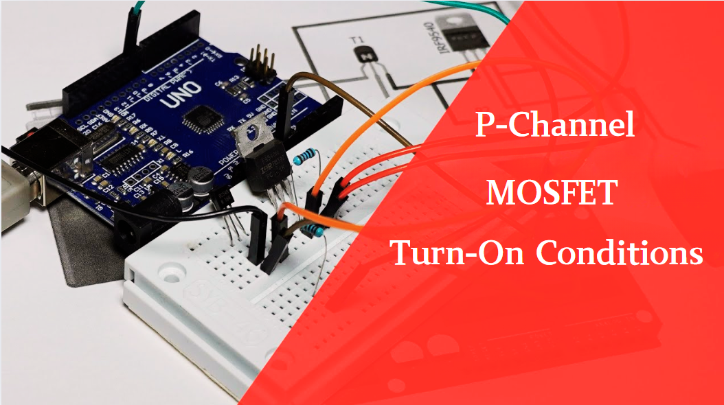
P-Channel MOSFET Turn-On Conditions
The turn-on conditions for a P-channel MOSFET (PMOS) are inverse to those of an N-channel MOSFET (NMOS), primarily governed by the relationship between the gate-source voltage (VGS) and the threshold voltage (Vth), along with voltage polarity. Here are the key points:A PMOS turns on when its gate vo...
-
2025 / 06 / 24
A8304SESTR-T Allegro MicroSystems-Single LNB Supply and Control Voltage Regulator
The Allegro MicroSystems A8304SESTR-T is a single-channel Low Noise Block Regulator (LNBR). It integrates a monolithic boost converter with MOSFET, current sensing, and compensation. Featuring a 704 kHz switching frequency, it uses few external components. With an I²C-compatible interface, it offers...
-
2025 / 06 / 20
EG25GGC-128-SGNS by Quectel Wireless Solutions Co., Ltd: Features,Symbol,Footprint and Datasheet
The Quectel EG25GGC - 128 - SGNS is an LTE Cat 4 module optimized for M2M and IoT. Supporting 3GPP Rel. 11, it offers up to 150Mbps downlink and 50Mbps uplink. With global LTE/UMTS/GSM coverage, it's backward - compatible with EDGE/GPRS. Featuring multi - constellation GNSS (GPS, GLONASS, BeiDou, et...

2000+
Daily average RFQ Volume

30,000,000
Standard Product Unit

2800+
Worldwide Manufacturers

15,000 m2
In-stock Warehouse
 Wishlist (0 Items)