

- RFQ
- BOM
-
Contact Us
Tel: +86-0755-83501315
Email: sales@sic-components.com


- Chinese
- English
- French
- German
- Portuguese
- Spanish
- Russian
- Japanese
- Korean
- Arabic
- Irish
- Greek
- Turkish
- Italian
- Danish
- Romanian
- Indonesian
- Czech
- Afrikaans
- Swedish
- Polish
- Basque
- Catalan
- Esperanto
- Hindi
- Lao
- Albanian
- Amharic
- Armenian
- Azerbaijani
- Belarusian
- Bengali
- Bosnian
- Bulgarian
- Cebuano
- Chichewa
- Corsican
- Croatian
- Dutch
- Estonian
- Filipino
- Finnish
- Frisian
- Galician
- Georgian
- Gujarati
- Haitian
- Hausa
- Hawaiian
- Hebrew
- Hmong
- Hungarian
- Icelandic
- Igbo
- Javanese
- Kannada
- Kazakh
- Khmer
- Kurdish
- Kyrgyz
- Latin
- Latvian
- Lithuanian
- Luxembou..
- Macedonian
- Malagasy
- Malay
- Malayalam
- Maltese
- Maori
- Marathi
- Mongolian
- Burmese
- Nepali
- Norwegian
- Pashto
- Persian
- Punjabi
- Serbian
- Sesotho
- Sinhala
- Slovak
- Slovenian
- Somali
- Samoan
- Scots Gaelic
- Shona
- Sindhi
- Sundanese
- Swahili
- Tajik
- Tamil
- Telugu
- Thai
- Ukrainian
- Urdu
- Uzbek
- Vietnamese
- Welsh
- Xhosa
- Yiddish
- Yoruba
- Zulu
- Kinyarwanda
- Tatar
- Oriya
- Turkmen
- Uyghur
High Voltage Capacitor
1. Introduction https://www.sic-components.com/capacitors
High voltage capacitors are essential passive electronic components designed to store electrical charge and energy under high - voltage conditions. These capacitors play a crucial role in a wide range of applications across various industries, from power transmission and distribution to medical equipment, industrial processes, and aerospace. Their ability to handle elevated voltages sets them apart from standard capacitors, making them indispensable for systems that require high - power handling capabilities and reliable energy storage and release.
2. Structure and Working Principle
2.1 Structure
A high voltage capacitor typically consists of two main components: conductive plates and a dielectric material. The conductive plates, often made of metal such as aluminum, are responsible for storing the electrical charge. These plates are separated by the dielectric, which is an insulating material. The choice of dielectric is critical as it determines many of the capacitor's properties. Common dielectric materials for high voltage capacitors include ceramic, plastic films (such as polypropylene in film capacitors), oil - impregnated paper, and mica.
The construction may vary depending on the type of capacitor. For example, in film - foil capacitors, one or more layers of a plastic film dielectric are wound alternately with metal foil electrodes. Metallized film capacitors, on the other hand, have a film dielectric on which the metal electrode has been vapor - deposited, and the layers are wound into a convoluted roll. In ceramic capacitors, the ceramic material itself serves as both the dielectric and the structure for the capacitor, with metal contacts bonded to it.
2.2 Working Principle
The fundamental working principle of a high voltage capacitor is based on the storage of electrical energy in an electric field. When a voltage is applied across the two conductive plates of the capacitor, electrons are forced to accumulate on one plate, creating a negative charge, while the other plate becomes positively charged due to the deficiency of electrons. This separation of charge creates an electric field between the plates, and the energy is stored in this field.
Mathematically, the capacitance C, which is a measure of the capacitor's ability to store charge, is given by the formula C=d/kA, where A is the area of the electrodes, d is their separation, and k is a constant related to the dielectric material between the electrodes. A larger electrode area, a thinner dielectric (while maintaining electrical integrity), and a dielectric material with a high dielectric constant will result in a higher capacitance value.
3. Types of High Voltage Capacitors
3.1 Ceramic Capacitors https://www.sic-components.com/ceramic-capacitors
Ceramic capacitors use ceramic materials, such as barium titanate, as the dielectric. They are known for their compact size and relatively high voltage ratings, often suitable for medium - to - high - voltage applications in the kilovolt range. These capacitors have a low equivalent series resistance (ESR), which makes them ideal for high - frequency circuits. However, their capacitance values are generally lower compared to some other types, and their capacitance can be temperature - dependent. For example, ceramic Z5U capacitors (a Class III ceramic dielectric) have a relatively large capacitance change with temperature, while ceramic X7R capacitors offer better temperature stability and are suitable for bypassing and coupling applications in high - voltage circuits.
3.2 Film Capacitors https://www.sic-components.com/film-capacitors
Film capacitors are made from plastic films, with polypropylene and polyester being common choices. There are two main subtypes: film - foil capacitors and metallized film capacitors. Film - foil capacitors have layers of plastic film dielectric wound with metal foil electrodes, while metallized film capacitors have the metal electrode vapor - deposited directly onto the film dielectric. Film capacitors offer good stability, high pulse - handling capabilities, and in the case of metallized film capacitors, a self - healing property. When a breakdown occurs in a small area of the dielectric, the metal in that region can vaporize, isolating the damaged area and restoring the capacitor's functionality. They are widely used in power electronics, inverters, and pulse - power applications where high - voltage and high - current pulses are involved.
3.3 Oil - Filled Capacitors
Oil - filled capacitors use impregnated paper or polymer films in combination with mineral oil as the dielectric. These capacitors are designed to handle high to very high voltages, making them suitable for applications in power transmission and industrial equipment. The oil helps to improve the dielectric strength and provides better heat dissipation, allowing the capacitor to handle high - voltage surges effectively. They offer high energy density, but their main drawbacks include a relatively large size and the potential for oil leaks, which require careful handling and maintenance.
4. Performance Specifications
4.1 Capacitance Range and Tolerance
The capacitance range of high voltage capacitors can vary widely depending on the type and application. Ceramic capacitors may have capacitance values ranging from a few picofarads (pF) to several nanofarads (nF), while film capacitors and oil - filled capacitors can have much higher capacitance values, reaching into the microfarad uF range. Capacitance tolerance refers to the allowable deviation from the nominal capacitance value. It is expressed as a percentage of the total capacitance. For example, a capacitor with a capacitance tolerance of (+/- 5%) may have an actual capacitance value that can be anywhere from 95% to 105% of the stated nominal value.
4.2 Working DC Voltage (WVDC)
The working DC voltage is the maximum voltage that can be continuously applied to the capacitor at any temperature within its specified operating range, which is between a lower category temperature and the rated temperature. Exceeding this voltage can lead to dielectric breakdown, where the insulating properties of the dielectric material fail, causing a short - circuit and potentially damaging the capacitor and other components in the circuit. High voltage capacitors are designed with specific WVDC ratings, which can range from a few kilovolts to hundreds of kilovolts depending on the application requirements.
4.3 Insulation Resistance
Insulation resistance is defined as the ratio between an applied DC voltage and the resulting leakage current. A high insulation resistance is desirable as it indicates that the capacitor is effectively preventing the flow of current through the dielectric, which helps in maintaining the stored charge and reducing energy losses. Over time, factors such as temperature, humidity, and electrical stress can cause the insulation resistance to decrease, potentially leading to increased leakage current and reduced capacitor performance.
4.4 Dissipation Factor (DF)
The dissipation factor is the ratio between the resistive and reactive parts of a capacitor's impedance when a sinusoidal voltage at a specified frequency is applied. It represents the energy losses within the capacitor. A lower dissipation factor is better as it means that the capacitor is more efficient, with less energy being dissipated as heat. The dissipation factor can vary depending on the dielectric material, operating temperature, and frequency. For example, ceramic capacitors generally have a low dissipation factor, making them suitable for high - frequency applications, while electrolytic capacitors (which are not typically the first choice for high voltage but can be used in some power - supply - related high - voltage applications) may have a relatively higher dissipation factor.
4.5 Temperature Coefficient
The temperature coefficient is a measure of the change in capacitance over a range of temperatures. Different dielectric materials have different temperature coefficients. Some materials, like certain ceramic formulations, can have a positive or negative temperature coefficient, which means the capacitance can increase or decrease with temperature. In applications where stable capacitance is crucial, capacitors with low - temperature coefficients, such as NPO (Negative - Positive - Zero) ceramic capacitors, are preferred. These capacitors have very predictable temperature coefficients and generally do not age significantly with time.
5. Mounting and Packaging
5.1 Mounting TypesHigh voltage capacitors can be mounted in several ways. Axial - lead capacitors have leads that extend from opposite ends of the capacitor body, while radial - lead capacitors have leads that extend from one side of the body. Flying leads are long, flexible leads that can be bent and soldered as needed. Tab - mounted capacitors have flat tabs for connection, and screw - mounted capacitors are attached using screws, providing a more secure connection for larger or higher - power capacitors. Gull - wing and J - leads are also used, especially in surface - mount - technology (SMT) - compatible capacitors. Some high voltage capacitors may require or come with mounting brackets, and pole - mounted capacitors are available for outdoor power - related applications.
5.2 Packaging Types
High voltage capacitors are packaged in various forms for ease of handling, storage, and assembly. Tape - reel packaging is common for small - to - medium - sized capacitors. The capacitor is placed in embossed cavities of a carrier tape, which is then sealed with a cover tape and wound on a reel. This type of packaging is suitable for automated pick - and - place equipment used in printed circuit board (PCB) assembly. Trays or rails are used for capacitors with leads on four sides. These are made of carbon - powder or fiber materials and are molded into rectangular outlines with uniformly spaced pockets to hold the capacitors. Shipping tubes or stick magazines, made of rigid polyvinyl chloride (PVC), are used to transport capacitors in a protected manner. Bulk packs are used when capacitors are distributed as individual parts, often for larger - scale applications where automated assembly is not the primary concern.
6. Applications
6.1 Power Transmission and Distribution
Power Factor Correction: In power systems, high voltage capacitors are used to improve the power factor. Inductive loads in the grid, such as motors and transformers, cause the current to lag behind the voltage, resulting in a lower power factor. By connecting high voltage capacitors in parallel with these inductive loads, reactive power is provided, reducing the overall reactive power demand from the grid. This leads to more efficient power transmission as less current needs to flow through the lines to deliver the same amount of real power, reducing line losses.
Voltage Stabilization: High voltage capacitors help in stabilizing the voltage in the power grid. They can absorb or supply reactive power depending on the grid conditions. For example, during periods of low load when the voltage tends to rise, the capacitors can be switched out of the circuit. Conversely, during high - load periods when the voltage drops, the capacitors can be connected to inject reactive power and boost the voltage. In a substation, banks of high voltage capacitors are used as part of a reactive - power - compensation system to maintain the voltage within acceptable limits.
Filtering: In power systems with non - linear loads (such as those containing power electronics devices), high voltage capacitors are used in combination with inductors to form filters. These filters are designed to remove harmonic currents from the power system. Harmonics can cause problems such as overheating of transformers and motors, interference with communication systems, and reduced efficiency of power equipment. The capacitors in the filter circuits are designed to resonate at specific harmonic frequencies, providing a low - impedance path for the harmonic currents to flow into, thereby preventing them from entering the main power grid.
6.2 Medical Equipment
X - ray Machines: High voltage capacitors are a crucial part of X - ray machines. In an X - ray generator, a high - voltage pulse is required to accelerate electrons towards a target material (such as tungsten). The high voltage capacitors store the energy needed to generate these high - voltage pulses. They are designed to deliver a large amount of energy in a short period, enabling the production of X - rays with the necessary intensity for medical imaging. The reliability and precise control of the high voltage provided by the capacitors are essential for obtaining clear and accurate X - ray images.
Defibrillators: In a defibrillator, high voltage capacitors are used to store the electrical energy required to deliver a life - saving shock to a patient's heart. When a heart is in an abnormal rhythm (such as ventricular fibrillation), a high - energy electrical shock can sometimes restore normal rhythm. The capacitors in a defibrillator are charged to a high voltage (usually several kilovolts) and then rapidly discharged through the patient's chest via electrodes. The ability of the high voltage capacitors to store and release this large amount of energy quickly and safely is critical for the effectiveness of the defibrillator.
6.3 Industrial Applications
Industrial Lasers: High voltage capacitors play a vital role in industrial laser systems. Lasers used in cutting, welding, and marking applications often require high - energy pulses to generate the intense light beam. The high voltage capacitors store the electrical energy and then release it in a short, high - power pulse to pump the laser medium (such as a gas, solid - state crystal, or semiconductor). The precise control of the energy delivered by the capacitors affects the quality and power of the laser beam, ensuring accurate and efficient industrial processes.
Welding Equipment: In certain types of welding, such as capacitor - discharge welding, high voltage capacitors are used. The capacitors are charged to a high voltage and then discharged through the welding electrodes. The sudden release of energy generates a high - current pulse that heats and fuses the metal parts being welded. This method is useful for welding thin materials or for making spot welds where a quick, high - energy burst is required.
6.4 Aerospace and Defense
Radar Systems: High voltage capacitors are used in radar transmitters to generate the high - power pulses needed to transmit radar signals. The capacitors store the electrical energy and then release it in short, intense pulses to drive the radar transmitter. The ability of the capacitors to handle high voltages and deliver high - power pulses is crucial for the long - range detection and accurate targeting capabilities of radar systems.
Electronic Warfare Equipment: In electronic warfare, high voltage capacitors are used in devices such as jammers and radar - warning receivers. Jammers use high - power signals to disrupt the enemy's radar and communication systems. High voltage capacitors help in generating these high - power jamming signals. In radar - warning receivers, high voltage capacitors are part of the circuits that detect and analyze incoming radar signals, providing early warning to military aircraft or vehicles.
Directed Energy Weapons: Some directed energy weapons, such as high - power microwave weapons, rely on high voltage capacitors to store and deliver the large amounts of electrical energy needed to generate intense microwave pulses. These pulses can be used to disable or damage enemy electronics and communication systems.
6.5 Renewable Energy Systems
Wind Turbines: High voltage capacitors are used in the power - conversion systems of wind turbines. They help in grid integration by compensating for reactive power. Wind turbines produce variable power depending on wind speed, and the capacitors can adjust the reactive - power output to match the requirements of the grid. This ensures stable operation of the wind turbine and helps in maintaining the power quality of the electricity fed into the grid.
Solar Power Plants: In solar power plants, high voltage capacitors are used in inverters that convert the direct current (DC) generated by solar panels into alternating current (AC) for use in the grid. The capacitors are part of the filtering and power - factor - correction circuits in the inverters. They help in reducing harmonic distortion in the output AC power and improving the overall efficiency of the power - conversion process.
7. Selection and Maintenance
7.1 Selection Considerations
Voltage Rating: The most critical factor in selecting a high voltage capacitor is ensuring that its voltage rating is sufficient for the application. The capacitor must be able to withstand the maximum voltage that it will encounter in the circuit, including any voltage surges or transients. Over - voltage can lead to dielectric breakdown and failure of the capacitor.
Capacitance Value: The required capacitance value depends on the specific function of the capacitor in the circuit. For example, in power - factor - correction applications, the capacitance value is calculated based on the reactive - power demand of the load. In filtering applications, the capacitance value is chosen in combination with inductance values to target specific harmonic frequencies.
Dielectric Material: The choice of dielectric material affects the capacitor's performance characteristics. Different dielectric materials have different temperature coefficients, dissipation factors, and voltage - handling capabilities. For high - frequency applications, materials with low dissipation factors, such as certain ceramic and film materials, are preferred. For applications where high energy density is required, oil - filled or certain film capacitors may be more suitable.
Operating Temperature Range: The capacitor must be able to operate within the temperature range of the application environment. Some dielectric materials may degrade or change their properties at high or low temperatures. For example, in aerospace applications where the temperature can vary widely, capacitors with a wide operating - temperature range, such as those with ceramic or certain film dielectrics, are often used.
Physical Size and Mounting: The physical size and mounting method of the capacitor need to be compatible with the available space in the circuit and the mechanical requirements of the application. In PCB - based applications, surface - mount or through - hole capacitors with appropriate lead configurations may be chosen. In larger power - system applications, capacitors with more robust mounting options, such as screw - mounted or pole - mounted capacitors, may be required.
Dielectric Materials and Performance Matching
Material Type Typical Voltage Range Temperature Coefficient High-Frequency Loss (DF) Application Scenarios
Ceramic (NPO/X7R) 1kV~30kV ±30ppm/℃~±1500ppm/℃ <0.1% (1MHz) High-frequency filtering, aerospace
Polypropylene Film (PP) 500V~10kV -100ppm/℃~+100ppm/℃ <0.01% (1kHz) Inverters, pulse power supplies
Oil-Impregnated Paper 10kV~300kV +500ppm/℃ 0.1%~0.5% High-voltage power transmission
Tantalum Electrolytic 50V~250V +800ppm/℃ 1%~5% Low-voltage high-capacitance energy storage (anti-reverse voltage required)
Environmental Adaptability Parameters
Temperature Range:
Industrial grade: -40℃~+85℃ (e.g., film capacitors);
Military grade: -55℃~+125℃ (e.g., NPO ceramic capacitors).
Humidity Protection: IP65 or higher for outdoor applications, with epoxy potting or metal-sealed enclosures.
Altitude Correction: For altitudes >1000m, reduce rated voltage per IEC 60664-1 (3% decrease per 1000m).
Mechanical Design and Mounting
Mounting Methods:
PCB level: Radial/axial leads, SMD (suitable for <1kV);
Industrial level: Bolted, flange-mounted (suitable for >10kV);
Outdoor level: Pole-mounted (with anti-vibration brackets).
Size Constraints: Film capacitors are preferred for high energy density scenarios (e.g., pulse power supplies), offering 40% smaller volume than oil-immersed capacitors.
7.2 Maintenance Procedures
Periodic Inspection Checklist
Item Testing Method Judgment Criteria
Visual Inspection Visual check for deformation, cracks, oil leakage No bulging, oil stains, or sealant cracking
Capacitance Measurement LCR bridge (1kHz) Deviation >±15% requires warning; >±20% requires replacement
Insulation Resistance 500V megohmmeter (DC) <1000MΩ indicates moisture ingress
Dissipation Factor Dielectric loss tester (50Hz) DF >0.5% (film) or >1% (ceramic) requires attention
Temperature Monitoring Infrared thermal imager/thermocouple Surface temperature > rated value +10℃ requires cooling modification
Special Maintenance Scenarios
Oil-Immersed Capacitors:
Test oil quality every 2 years (acid value <0.1mgKOH/g, breakdown voltage >35kV);
Vacuum degassing is required when refilling oil to prevent partial discharge from bubbles.
Pulse Capacitors:
Inspect pin soldering points after every 1000 pulses (prevent fatigue fracture);
Measure ESR in high-frequency applications (>2x initial value requires replacement).
Safety Operation Specifications
Discharge Process:
Wait 10 minutes after power disconnection (self-discharge);
Short-circuit terminals with a 100kΩ/50W resistor (wear insulated gloves);
Confirm voltage <30V with a multimeter before operation.
High-Voltage Area Warnings:
Require two personnel during maintenance; set "High Voltage Danger" signs;
Use remote probes for live testing (distance ≥0.7m @10kV).
8. Standards and Regulations
8.1 Design and Testing Standards
IEC 60143-1: High-Voltage Shunt Capacitors
Specifies capacitance tolerance (±5%), dielectric loss (<0.1%), and temperature cycle testing (-40℃~+70℃, 1000 cycles).
IEEE C57.16: American Shunt Capacitor Standard
Mandates internal fuse breaking capacity (≥1000A) and defines UV aging resistance criteria for outdoor capacitors.
8.2 Safety and Installation Codes
NFPA 70 (NEC):
Specifies fire resistance rating for high-voltage capacitor rooms (≥2 hours) and grounding resistance <5Ω.
GB 50227-2017 (China):
Design code for shunt capacitor banks, requiring discharge coil secondary voltage ≥100V and discharge time <5s.
8.3 Special Application Standards
Medical Equipment:
IEC 60601-1: Medical X-ray capacitors must pass 1.5x rated voltage withstand tests with leakage current <10μA.
Aerospace:
MIL-PRF-55681: Ceramic capacitors must pass 100g impact testing and temperature cycling (-55℃~+125℃, 100 cycles).
Regional Compliance Certifications
Region Certification Mark Key Requirements
European Union CE Compliance with EN 60143 and RoHS 3 restricted substances list
United States UL/cUL Flammability rating UL94 V-0, 1.8x rated voltage withstand test
China CCC EMC compliance with GB/T 17626 series
Russia EAC Low-temperature performance (capacitance deviation <±20% at -50℃)
Emerging Technical Standard Trends
New Energy Sector:
IEC 62933: Capacitors for photovoltaic inverters must withstand 1000V DC +300V ripple with a lifespan >20 years.
High-Frequency Power Electronics:
JEDEC JESD22-A114: Thermal cycle testing for high-frequency capacitors (-40℃~+125℃, 1000 cycles).
Environmental Requirements:
EU EuP Directive: Oil-immersed capacitors must use biodegradable oils (e.g., natural esters) by 2025.
Non-Compliance Risks and Cases
Accident Lessons:
In 2023, a substation fire caused by uncertified capacitor breakdown led to direct losses exceeding CNY 5 million (violating GB 50227);
In 2024, a medical device manufacturer was fined USD 2 million for capacitor leakage causing patient electric shock (violating IEC 60601).
Regulatory Trends:
The EU has mandated CE-TAM labels for high-voltage capacitors since 2024, specifying full lifecycle compliance information.
Through systematic selection evaluation, standardized maintenance, and end-to-end compliance, the annual failure rate of high-voltage capacitors can be controlled below 0.5%, significantly enhancing system reliability and safety. Enterprises are advised to establish a full-cycle management file covering "selection-installation-maintenance-disposal" to ensure compliance with the latest international and regional regulations.
https://www.sic-components.com/capacitors
Hot Products
View More-

61F-G3NR AC110/220 Omron Automation and Safety
-
61F-GP-NH AC200 Omron Automation and Safety
-
84870404 Crouzet
-
61F-GP-N2 240 Omron Automation and Safety
-
PC-100-LLC-GM Littelfuse Inc.
-

NNR220A Crouzet
-
NNR24A Crouzet
-
LC-F-3-C-N3 Curtis Industries
-
LC-F-3-N3 Curtis Industries
-
ATS-LD-14 Advanced Thermal Solutions Inc.
-
61F-GP-N2 24VAC Omron Automation and Safety
-

SPM-120-AEAS-100K Mueller Electric Co
Related Blogs
-
2025 / 07 / 09
CD4007: A Comprehensive Analysis of a Multifunctional CMOS Integrated Circuit
In the field of modern electronic technology, CMOS (Complementary Metal-Oxide-Semiconductor) integrated circuits have become core components in digital and analog circuit design due to their low power consumption, high integration, and excellent compatibility. As a classic CMOS device, the CD4007 oc...

-
2025 / 07 / 07
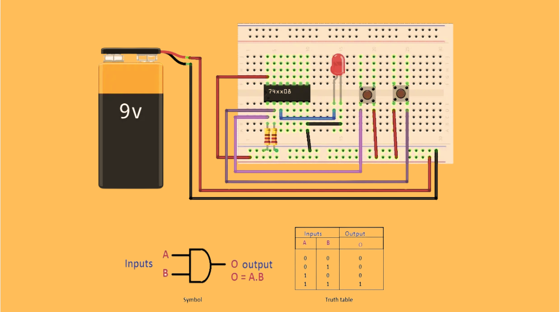
Understanding IC 7408: A Fundamental Component in Digital Logic Design
In the vast and intricate realm of digital electronics, integrated circuits (ICs) serve as the building blocks that enable the creation of complex and powerful systems. Among these, the IC 7408 holds a special place as a fundamental component in digital logic design. This article aims to provide a c...
-
2025 / 07 / 04
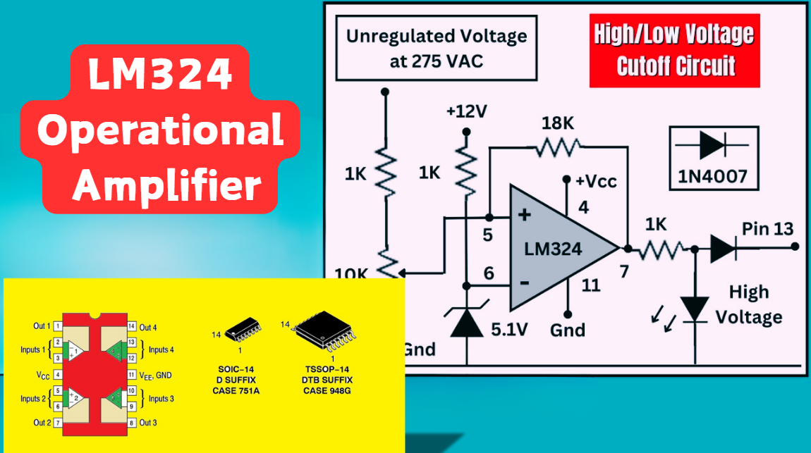
LM324 Operational Amplifier Comprehensive Guide: Pins, Applications, Packaging, and Datasheet
The LM324 is a low-cost integrated circuit featuring four independent operational amplifiers (op-amps), renowned for its wide voltage adaptability, low power consumption, and high reliability in industrial and consumer electronics. With a single-supply voltage range of 3V to 32V (or dual-supply rang...
-
2025 / 07 / 02
A Comprehensive Guide to Replacing Opto-Couplers with Digital Isolators: From Principles to Practice
In the ever-evolving landscape of electronic design, the transition from opto-couplers to digital isolators marks a pivotal shift in isolation technology. For decades, opto-couplers have been the cornerstone of electrical isolation in industrial control, medical devices, and power systems, relying o...
-
2025 / 06 / 30
Multivariate Application Analysis of Power Amplifiers in Sensor Testing
In the field of modern sensor testing, power amplifiers (PAs) serve as core components and play an indispensable role. From amplifying weak signals to simulating complex physical environments, power amplifiers provide solid guarantees for the precise testing of sensor performance through their uniqu...
-
2025 / 06 / 28
ESP32 vs STM32: Which Microcontroller Suits You Better?
In the field of embedded development, both ESP32 and STM32 are highly favored microcontrollers, each with unique features and advantages. When facing project development, how do you choose between them? This requires comprehensive consideration of multiple factors. The following detailed comparison ...
-
2025 / 06 / 26
Key Strategies to Enhance Buck Power Supply Efficiency
Improving the efficiency of Buck (step-down) switching power supplies requires a multi-dimensional approach targeting energy loss sources, including component selection, topology optimization, control strategies, and thermal management. Below are core strategies and engineering practices:...
-
2025 / 06 / 26
P-Channel MOSFET Turn-On Conditions
The turn-on conditions for a P-channel MOSFET (PMOS) are inverse to those of an N-channel MOSFET (NMOS), primarily governed by the relationship between the gate-source voltage (VGS) and the threshold voltage (Vth), along with voltage polarity. Here are the key points:A PMOS turns on when its gate vo...
-
2025 / 06 / 24
A8304SESTR-T Allegro MicroSystems-Single LNB Supply and Control Voltage Regulator
The Allegro MicroSystems A8304SESTR-T is a single-channel Low Noise Block Regulator (LNBR). It integrates a monolithic boost converter with MOSFET, current sensing, and compensation. Featuring a 704 kHz switching frequency, it uses few external components. With an I²C-compatible interface, it offers...
-
2025 / 06 / 20
EG25GGC-128-SGNS by Quectel Wireless Solutions Co., Ltd: Features,Symbol,Footprint and Datasheet
The Quectel EG25GGC - 128 - SGNS is an LTE Cat 4 module optimized for M2M and IoT. Supporting 3GPP Rel. 11, it offers up to 150Mbps downlink and 50Mbps uplink. With global LTE/UMTS/GSM coverage, it's backward - compatible with EDGE/GPRS. Featuring multi - constellation GNSS (GPS, GLONASS, BeiDou, et...


2000+
Daily average RFQ Volume

30,000,000
Standard Product Unit

2800+
Worldwide Manufacturers

15,000 m2
In-stock Warehouse
 Wishlist (0 Items)