

- RFQ
- BOM
-
Contact Us
Tel: +86-0755-83501315
Email: sales@sic-components.com


- Chinese
- English
- French
- German
- Portuguese
- Spanish
- Russian
- Japanese
- Korean
- Arabic
- Irish
- Greek
- Turkish
- Italian
- Danish
- Romanian
- Indonesian
- Czech
- Afrikaans
- Swedish
- Polish
- Basque
- Catalan
- Esperanto
- Hindi
- Lao
- Albanian
- Amharic
- Armenian
- Azerbaijani
- Belarusian
- Bengali
- Bosnian
- Bulgarian
- Cebuano
- Chichewa
- Corsican
- Croatian
- Dutch
- Estonian
- Filipino
- Finnish
- Frisian
- Galician
- Georgian
- Gujarati
- Haitian
- Hausa
- Hawaiian
- Hebrew
- Hmong
- Hungarian
- Icelandic
- Igbo
- Javanese
- Kannada
- Kazakh
- Khmer
- Kurdish
- Kyrgyz
- Latin
- Latvian
- Lithuanian
- Luxembou..
- Macedonian
- Malagasy
- Malay
- Malayalam
- Maltese
- Maori
- Marathi
- Mongolian
- Burmese
- Nepali
- Norwegian
- Pashto
- Persian
- Punjabi
- Serbian
- Sesotho
- Sinhala
- Slovak
- Slovenian
- Somali
- Samoan
- Scots Gaelic
- Shona
- Sindhi
- Sundanese
- Swahili
- Tajik
- Tamil
- Telugu
- Thai
- Ukrainian
- Urdu
- Uzbek
- Vietnamese
- Welsh
- Xhosa
- Yiddish
- Yoruba
- Zulu
- Kinyarwanda
- Tatar
- Oriya
- Turkmen
- Uyghur
Power Supply Components: A Comprehensive Guide to Essential Elements and Their Functions
1. Introduction to Power Supply Components https://www.sic-components.com/power-supply-controllers-monitors
Power supply systems are the backbone of electronic devices, converting incoming electrical energy into usable forms for components. The reliability and performance of a power supply depend on the synergy of its components, each playing a critical role in voltage conversion, regulation, and protection. This article dissects the key components of modern power supplies, from traditional linear designs to advanced switch-mode systems, exploring their functions, design considerations, and real-world applications.
2. Transformer: The Voltage Conversion Core
2.1 Function and Principles
A transformer is a magnetic component that steps up or steps down alternating current (AC) voltage using electromagnetic induction. In power supplies, it primarily reduces high mains voltage (e.g., 220VAC) to a lower level suitable for rectification and regulation. Key features include:
Isolation: Separates the mains from the output circuit, enhancing safety by eliminating direct electrical contact.
Turn Ratio: Determines voltage conversion (e.g., a 10:1 ratio steps 220VAC down to 22VAC).
Core Materials: Ferrite (high-frequency applications) or laminated iron (low-frequency, high-power use).
2.2 Types and Applications
Step-Down Transformers: Most common in power supplies, e.g., converting 110/220VAC to 12/24VAC for rectification.
Isolation Transformers: 1:1 turn ratio, used to prevent ground loops and electrical shocks in line-operated circuits.
Planar Transformers: Flat, low-profile design for high-frequency switch-mode power supplies (SMPS), reducing parasitic inductance.
2.3 Design Considerations
Power Rating: Must handle the supply’s maximum output power (e.g., a 100W supply needs a transformer with ≥120W capacity).
Efficiency: Core losses (hysteresis and eddy currents) should be minimized; ferrite cores excel at >20kHz.
Size and Cooling: Larger transformers with iron cores require heat dissipation, while SMPS transformers are compact.
3. Rectifiers: Converting AC to Pulsating DC
3.1 Diode Fundamentals
Rectifiers use diodes to convert AC to direct current (DC) by allowing current flow in one direction. Key diode types for rectification:
Silicon Diodes: Standard 1N4007 (1A, 1000V) for low-power supplies; 1N5408 (3A, 1000V) for higher currents.
Schottky Diodes: Lower forward voltage drop (0.3–0.5V) than silicon diodes, ideal for low-voltage, high-efficiency SMPS (e.g., MBR1060, 10A, 60V).
Fast Recovery Diodes: Reduced reverse recovery time for high-frequency applications (e.g., FR107, 1A, 1000V, trr=500ns).
3.2 Rectifier Topologies
Half-Wave Rectifier
Circuit: 1 diode + load; conducts only half the AC cycle.
Efficiency: ~40%; outputs pulsating DC at input frequency (e.g., 60Hz for 60Hz AC).
Use Cases: Rare in practical supplies due to low efficiency; may appear in simple battery chargers.
Full-Wave Rectifier (Center-Tapped)
Circuit: 2 diodes + center-tapped transformer; conducts both AC half-cycles.
Efficiency: ~80%; output ripple frequency doubles (e.g., 120Hz for 60Hz input).
Example: Vintage audio amplifiers, some low-power linear supplies.
Bridge Rectifier
Circuit: 4 diodes in a bridge configuration; uses full transformer secondary voltage.
Efficiency: ~80%; ripple frequency = 2× input frequency.
Integrated Modules: e.g., GBPC1510 (15A, 1000V) for high-power supplies; compact SMD bridges for SMPS.
3.3 Design Tips
Peak Inverse Voltage (PIV): Diodes must withstand PIV ≥1.414× peak input voltage (e.g., 1N4007 PIV=1000V suits 220VAC mains).
Heat Dissipation: High-current diodes (e.g., 10A+) may require heat sinks; Schottky diodes generate less heat.
4. Filters: Smoothing Pulsating DC
4.1 Capacitor Filters
Electrolytic Capacitors
Function: Store charge during rectifier conduction, discharge into the load to reduce ripple.
Key Parameters:
Capacitance: 10μF–2200μF; larger values reduce ripple (e.g., 1000μF for 12V/1A supply).
Voltage Rating: ≥1.414× peak rectified voltage (e.g., 25V for 12V output).
ESR (Equivalent Series Resistance): Lower ESR (≤50mΩ) minimizes ripple voltage (e.g., low-ESR low-profile caps for SMPS).
Polarity: Must be connected correctly; reverse voltage causes explosion.
Ceramic Capacitors
Function: High-frequency ripple suppression; parallel with electrolytics.
Types: X7R/X5R dielectrics (100nF–10μF) for stability; Y5V for cost-sensitive applications.
Placement: Within 5mm of the output to minimize parasitic inductance.
4.2 Inductor Filters (Chokes)
Function: Oppose current changes, smoothing ripple in LC or π filters.
Core Materials:
Iron powder: 100μH–30H for low-frequency linear supplies.
Ferrite: 1μH–100μH for SMPS, high permeability at 100kHz–1MHz.
Current Rating: Must exceed the supply’s maximum output current (e.g., 2A choke for 1.5A supply).
4.3 Filter Topologies
Capacitor Input Filter
Circuit: Capacitor across rectifier output; simplest design.
Output Voltage: ~1.414× transformer secondary voltage (e.g., 12VAC → ~17VDC unloaded).
Ripple Calculation:Vripple = Iload/(f×C) (e.g., 1A load, 1000μF, 120Hz → 8.3mV ripple).
LC Filter (L-Section)
Circuit: Inductor in series, capacitor in parallel with load.
Advantages: Lower ripple, better load regulation; suitable for high-current supplies.
π Filter (Capacitor-Inductor-Capacitor)
Circuit: Two capacitors sandwiching an inductor; optimal ripple reduction.
Use Cases: Audio amplifiers, medical equipment requiring <10mV ripple.
5. Voltage Regulators: Ensuring Stable Output
5.1 Linear Regulators
Fixed Voltage Regulators
3-Terminal Devices:
78xx Series (positive voltage): e.g., 7805 (5V/1A), 7812 (12V/1A).
79xx Series (negative voltage): e.g., 7905 (-5V/1A).
Internal Structure: Pass transistor, error amplifier, voltage reference (e.g., 2.5V Zener).
Dropout Voltage: Minimum input-output voltage difference (e.g., 7805 requires ≥2V dropout, 5V output needs ≥7V input).
Adjustable Regulators
Example: LM317 (positive, 1.25V–37V, 1.5A).
Output Voltage: Set by two resistors:Vout = 1.25V*(1 +R2/R1) (e.g., R1=240Ω, R2=240Ω → 2.5V output).
Low-Dropout (LDO) Regulators
Dropout Voltage: <1V (e.g., AMS1117: 1.2V dropout at 1A).
Applications: Battery-powered devices, sensitive RF circuits (low noise).
5.2 Switching Regulators
Buck (Step-Down) Regulators
Topology: PWM-controlled switch, inductor, diode, output capacitor.
Efficiency: 80–95%; e.g., LM2576 (3A, 40V input, 1.23–37V output, 92% efficient).
Switching Frequency: 50kHz–2MHz; higher frequencies allow smaller inductors/capacitors.
Boost (Step-Up) Regulators
Topology: Switch, inductor, diode, output capacitor; increases voltage.
Example: MC34063 (28V max, 1.5A, converts 5V to 12V at 85% efficiency).
Buck-Boost Regulators
Function: Output voltage can be higher or lower than input (e.g., LT8302, 40V, 2.5A).
Applications: Battery-powered devices (3.7V Li-ion → 5V output, even as battery voltage drops).
5.3 Design Considerations
Efficiency vs. Noise: Linear regulators are quiet but inefficient; switching regulators are efficient but may cause EMI.
Thermal Management: Linear regulators dissipate heat (e.g., 7805 at 1A, 5V output from 12V input: Pd = (12-5)×1=7W, requires heat sink).
Load Regulation: Switching regulators maintain voltage better under varying loads (≤±0.5%), vs. linear regulators (≤±1%).
6. Protection Circuits: Safeguarding the Supply
6.1 Overvoltage Protection (OVP)
Zener Diode Clamp: Zener diode in parallel with output; conducts if voltage exceeds rating (e.g., 12V Zener clamps output to 12V + 0.7V).
Active OVP: Comparator + MOSFET shuts down the supply or diverts current (e.g., TL431-based circuit for precise voltage monitoring).
6.2 Overcurrent Protection (OCP)
Fuse: Fast-blow fuse (e.g., 2A/250V) in series with input; blows during short circuits.
Current Limiting: Resistor + transistor limits current (e.g., in linear regulators:Rsense= 0.7V/IIimit} , 0.7V is base-emitter voltage of a BJT).
6.3 Thermal Protection
Thermistor: NTC (negative temperature coefficient) thermistor in the supply’s heat path; triggers shutdown if temperature exceeds threshold (e.g., 100°C).
Thermal Trip Circuit: Bimetallic switch or thermal diode integrated into ICs (e.g., LM2596 switching regulator shuts down at 150°C).
6.4 EMI Filters
Common-Mode Choke: Suppresses differential noise; two windings on a ferrite core (e.g., 10mH, 1A for SMPS input).
X/Y Capacitors:
X caps (across lines):Suppress differential noise (e.g., 0.1μF/275VAC X2 class).
Y caps (line to ground):Suppress common-mode noise (e.g., 2200pF/400VAC Y2 class).
7. Input Filters: Mitigating Mains Disturbances
7.1 EMI/RFI Filters
Function: Block high-frequency noise from the mains (100kHz–30MHz) and prevent supply-generated noise from entering the grid.
Components:
Common-mode choke (CM choke): Attenuates common-mode noise.
Differential-mode capacitor (X cap): Attenuates differential noise.
Standards Compliance: Must meet EN 55032 (EMI) and IEC 61000-3-2 (harmonics).
7.2 Surge Protection
Metal-Oxide Varistor (MOV): Connected across input; clamps voltage during surges (e.g., 275VAC MOV for 220V mains).
Gas Discharge Tube (GDT): High-voltage surge protection (e.g., 250V GDT for lightning strikes).
8. Auxiliary Components
8.1 Heat Sinks
Aluminum Extrusions: For linear regulators (e.g., TO-220 package, Rth=5°C/W).
Thermal Paste: Enhances heat transfer (e.g., Arctic Silver 5, thermal conductivity 8.5 W/m·K).
8.2 Indicators
LEDs: Power-on indicator (e.g., 10mA through a 1kΩ resistor for 12V supply).
Voltage/Current Meters: Analog or digital displays for monitoring output.
8.3 Connectors
Input: IEC 60320 C14 (mains plug), Output: Barrel jacks (2.1mm/5.5mm), terminal blocks.
9. System Integration and Design Examples
9.1 12V/2A Linear Power Supply
Block Diagram: 220VAC → transformer (220V→15VAC) → bridge rectifier → 2200μF/25V cap → 7812 regulator → 100μF/16V cap → 12V/2A output.
Efficiency: ~50% (7812 drops 3V at 12V output from 15V rectified input: (12/15)×100=80%, minus regulator losses).
9.2 5V/3A Switching Power Supply (SMPS)
Block Diagram: 220VAC → EMI filter → bridge rectifier → 470μF/400V cap → switching controller (e.g., LM5146) → 4.7μH inductor → 1000μF/10V low-ESR cap → 5V/3A output.
Efficiency: ~90% (220VAC→5V/3A: input power ≈ (5×3)/0.9=16.7W, vs. linear supply’s ~30W input).
10. Advanced Components and Trends
10.1 Wide-Bandgap (WBG) Devices
GaN/SiC Diodes and MOSFETs:
GaN diodes: Ultra-fast switching (trr<10ns), low capacitance (e.g., EPC2059, 100V/30A).
SiC MOSFETs: High voltage (1200V), low RDS(on) (20mΩ), ideal for high-efficiency SMPS.
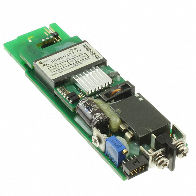
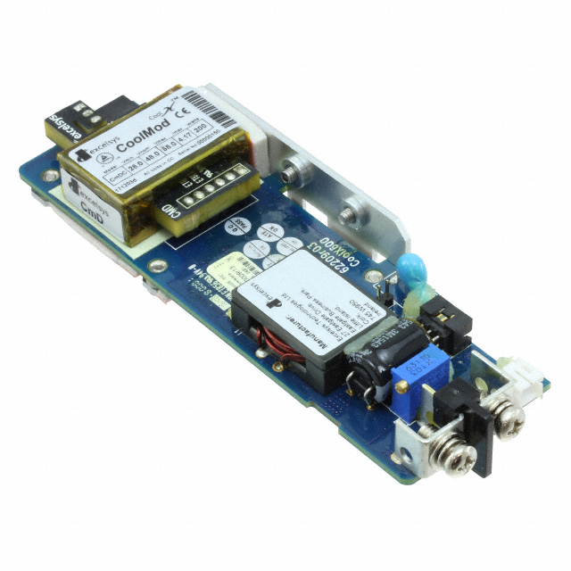
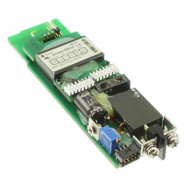
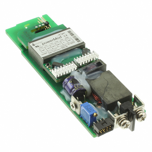
10.2 Integrated Power Modules
Example: Vicor VIA series (1500V isolation, 98% efficiency, 48V→12V/50A).
Advantages: Pre-integrated controller, MOSFETs, inductors; reduces design time and PCB space.
10.3 Digital Power Management
PMBus-Enabled Regulators:
TI’s LM5146: Digital control via I2C, real-time monitoring of voltage/current/temperature.
Adaptive Voltage Scaling: Adjusts output voltage based on load, optimizing efficiency in data centers.
11. Safety and Compliance
11.1 Electrical Safety
Isolation Voltage: Transformers must withstand ≥3000VAC between primary and secondary for safety.
Grounding: Class I supplies require a earth ground; Class II (double-insulated) do not.
11.2 Regulatory Standards
IEC 60950-1: Safety for IT equipment.
UL 62368-1: Audio/video, information, and communication technology equipment.
RoHS: Restricts lead, mercury, etc., in components (e.g., lead-free solder).
Conclusion
Power supply components work in tandem to convert, regulate, and protect electrical energy, ensuring reliable operation of electronic systems. From transformers and rectifiers to advanced WBG devices, each component plays a crucial role in balancing efficiency, stability, and safety. As technology evolves toward higher power densities and smarter management, understanding these components—their strengths, limitations, and integration—is essential for designing robust power supplies that meet the demands of modern electronics. Whether for a simple hobby project or a complex industrial system, careful component selection and design remain the foundation of successful power supply engineering.
https://www.sic-components.com/power-supply-controllers-monitors
Hot Products
View More-
CMCC Advanced Energy
-

C3S-000000000000-NA Advanced Energy
-

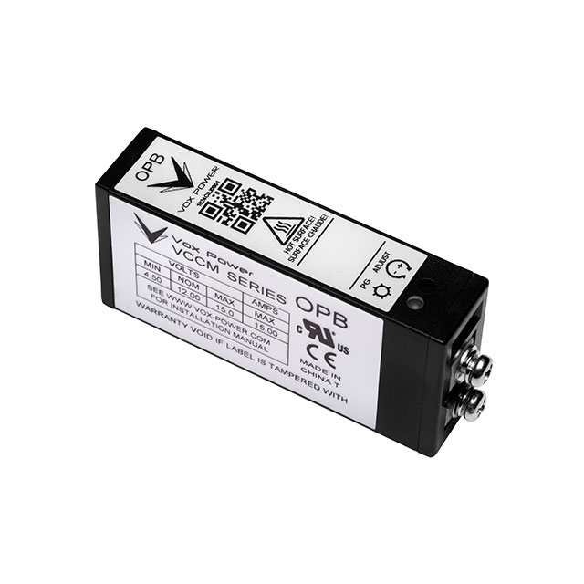
OP5 Vox Power Ltd.
-

C150S05 Sanken Electric USA Inc.
-
XG4 Advanced Energy
-
C130X24 Sanken Electric USA Inc.
-
XGFC Advanced Energy
-
XG3C Advanced Energy
-
XGMC Advanced Energy
-
H40935 TDK-Lambda Americas Inc
-
XG5 Advanced Energy
-

NMD-240 MEAN WELL USA Inc.
Related Blogs
-
2025 / 07 / 09
CD4007: A Comprehensive Analysis of a Multifunctional CMOS Integrated Circuit
In the field of modern electronic technology, CMOS (Complementary Metal-Oxide-Semiconductor) integrated circuits have become core components in digital and analog circuit design due to their low power consumption, high integration, and excellent compatibility. As a classic CMOS device, the CD4007 oc...

-
2025 / 07 / 07
Understanding IC 7408: A Fundamental Component in Digital Logic Design
In the vast and intricate realm of digital electronics, integrated circuits (ICs) serve as the building blocks that enable the creation of complex and powerful systems. Among these, the IC 7408 holds a special place as a fundamental component in digital logic design. This article aims to provide a c...
-
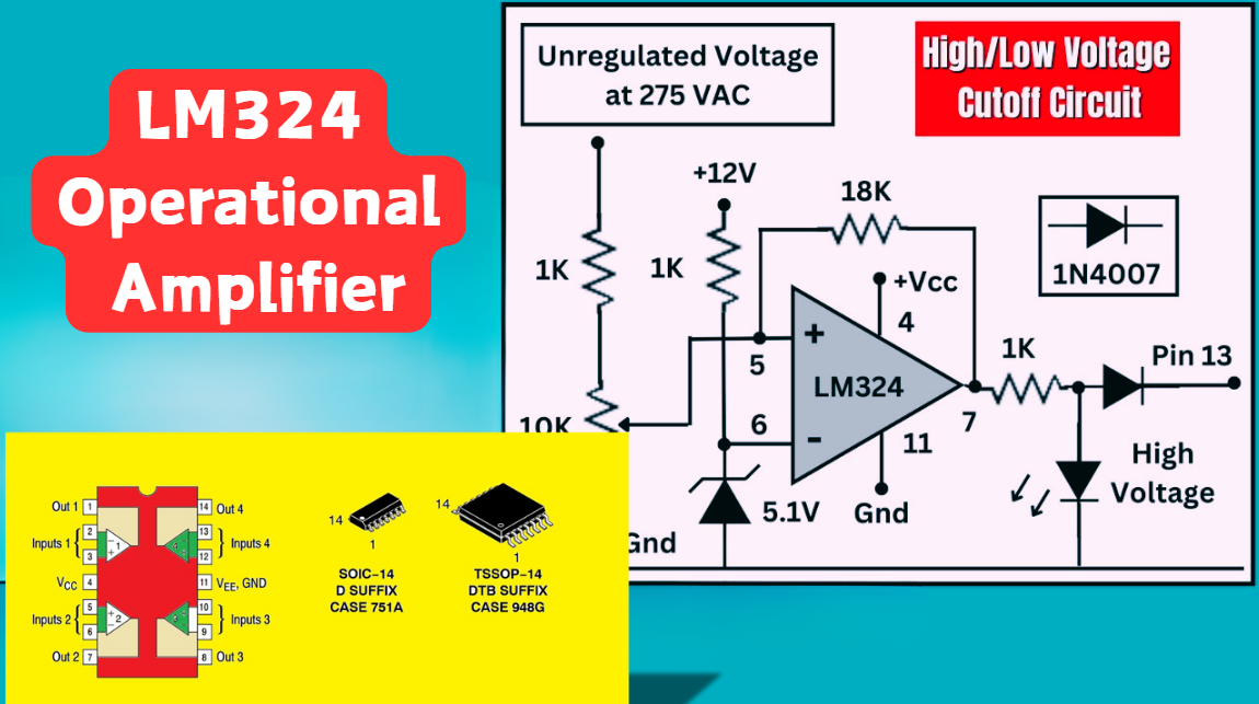
2025 / 07 / 04
LM324 Operational Amplifier Comprehensive Guide: Pins, Applications, Packaging, and Datasheet
The LM324 is a low-cost integrated circuit featuring four independent operational amplifiers (op-amps), renowned for its wide voltage adaptability, low power consumption, and high reliability in industrial and consumer electronics. With a single-supply voltage range of 3V to 32V (or dual-supply rang...
-
2025 / 07 / 02
A Comprehensive Guide to Replacing Opto-Couplers with Digital Isolators: From Principles to Practice
In the ever-evolving landscape of electronic design, the transition from opto-couplers to digital isolators marks a pivotal shift in isolation technology. For decades, opto-couplers have been the cornerstone of electrical isolation in industrial control, medical devices, and power systems, relying o...
-
2025 / 06 / 30
Multivariate Application Analysis of Power Amplifiers in Sensor Testing
In the field of modern sensor testing, power amplifiers (PAs) serve as core components and play an indispensable role. From amplifying weak signals to simulating complex physical environments, power amplifiers provide solid guarantees for the precise testing of sensor performance through their uniqu...
-
2025 / 06 / 28
ESP32 vs STM32: Which Microcontroller Suits You Better?
In the field of embedded development, both ESP32 and STM32 are highly favored microcontrollers, each with unique features and advantages. When facing project development, how do you choose between them? This requires comprehensive consideration of multiple factors. The following detailed comparison ...
-
2025 / 06 / 26
Key Strategies to Enhance Buck Power Supply Efficiency
Improving the efficiency of Buck (step-down) switching power supplies requires a multi-dimensional approach targeting energy loss sources, including component selection, topology optimization, control strategies, and thermal management. Below are core strategies and engineering practices:...
-
2025 / 06 / 26
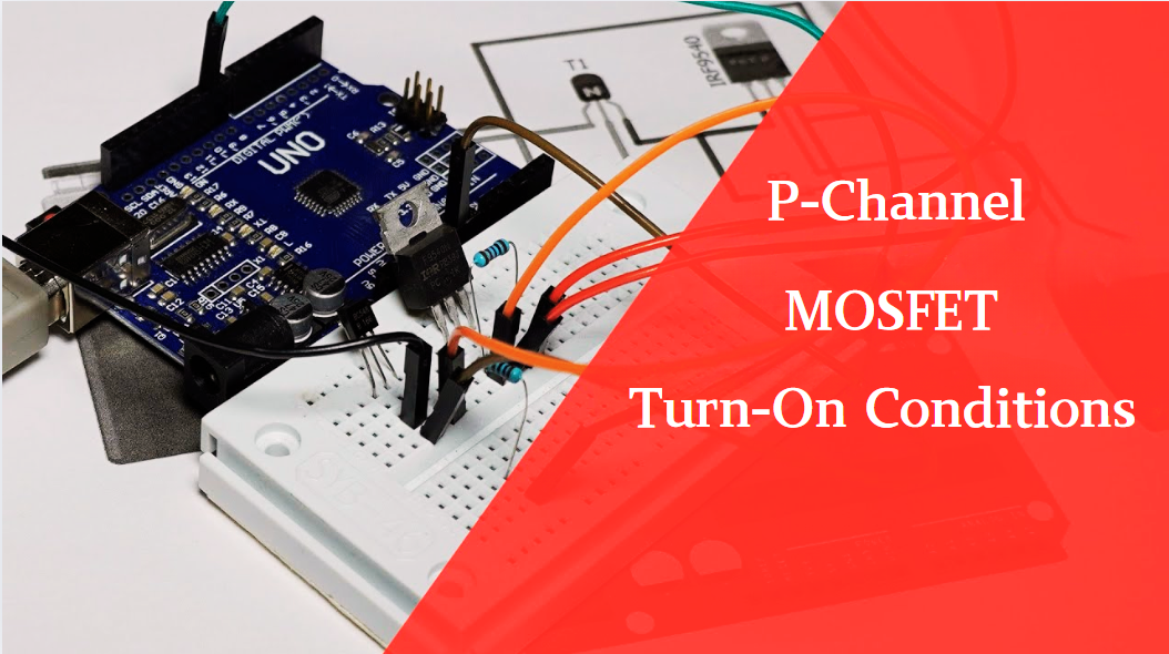
P-Channel MOSFET Turn-On Conditions
The turn-on conditions for a P-channel MOSFET (PMOS) are inverse to those of an N-channel MOSFET (NMOS), primarily governed by the relationship between the gate-source voltage (VGS) and the threshold voltage (Vth), along with voltage polarity. Here are the key points:A PMOS turns on when its gate vo...
-
2025 / 06 / 24
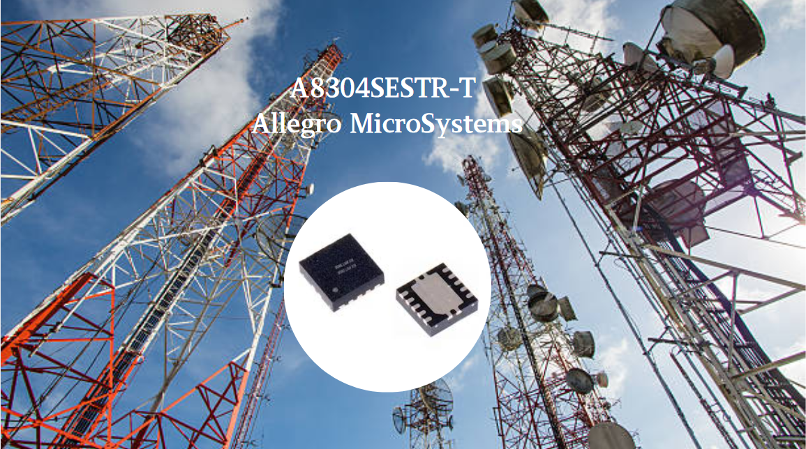
A8304SESTR-T Allegro MicroSystems-Single LNB Supply and Control Voltage Regulator
The Allegro MicroSystems A8304SESTR-T is a single-channel Low Noise Block Regulator (LNBR). It integrates a monolithic boost converter with MOSFET, current sensing, and compensation. Featuring a 704 kHz switching frequency, it uses few external components. With an I²C-compatible interface, it offers...
-
2025 / 06 / 20
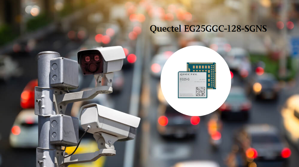
EG25GGC-128-SGNS by Quectel Wireless Solutions Co., Ltd: Features,Symbol,Footprint and Datasheet
The Quectel EG25GGC - 128 - SGNS is an LTE Cat 4 module optimized for M2M and IoT. Supporting 3GPP Rel. 11, it offers up to 150Mbps downlink and 50Mbps uplink. With global LTE/UMTS/GSM coverage, it's backward - compatible with EDGE/GPRS. Featuring multi - constellation GNSS (GPS, GLONASS, BeiDou, et...

2000+
Daily average RFQ Volume

30,000,000
Standard Product Unit

2800+
Worldwide Manufacturers

15,000 m2
In-stock Warehouse
 Wishlist (0 Items)