

- RFQ
- BOM
-
Contact Us
Tel: +86-0755-83501315
Email: sales@sic-components.com


- Chinese
- English
- French
- German
- Portuguese
- Spanish
- Russian
- Japanese
- Korean
- Arabic
- Irish
- Greek
- Turkish
- Italian
- Danish
- Romanian
- Indonesian
- Czech
- Afrikaans
- Swedish
- Polish
- Basque
- Catalan
- Esperanto
- Hindi
- Lao
- Albanian
- Amharic
- Armenian
- Azerbaijani
- Belarusian
- Bengali
- Bosnian
- Bulgarian
- Cebuano
- Chichewa
- Corsican
- Croatian
- Dutch
- Estonian
- Filipino
- Finnish
- Frisian
- Galician
- Georgian
- Gujarati
- Haitian
- Hausa
- Hawaiian
- Hebrew
- Hmong
- Hungarian
- Icelandic
- Igbo
- Javanese
- Kannada
- Kazakh
- Khmer
- Kurdish
- Kyrgyz
- Latin
- Latvian
- Lithuanian
- Luxembou..
- Macedonian
- Malagasy
- Malay
- Malayalam
- Maltese
- Maori
- Marathi
- Mongolian
- Burmese
- Nepali
- Norwegian
- Pashto
- Persian
- Punjabi
- Serbian
- Sesotho
- Sinhala
- Slovak
- Slovenian
- Somali
- Samoan
- Scots Gaelic
- Shona
- Sindhi
- Sundanese
- Swahili
- Tajik
- Tamil
- Telugu
- Thai
- Ukrainian
- Urdu
- Uzbek
- Vietnamese
- Welsh
- Xhosa
- Yiddish
- Yoruba
- Zulu
- Kinyarwanda
- Tatar
- Oriya
- Turkmen
- Uyghur
The Roles and Rules of Capacitors - PCB Design
Introduction
In the complex realm of Printed Circuit Board (PCB) design, capacitors stand as fundamental and versatile components. Their presence is not just ubiquitous but essential for the proper functioning of a vast array of electronic devices, from the tiniest wearables to large - scale industrial equipment. Understanding their roles and the rules governing their implementation in PCB design is crucial for creating efficient, reliable, and high - performing circuits.
The Roles of Capacitors in PCB Design
Signal Coupling and Isolation
Capacitors play a pivotal role in signal coupling between different circuit stages. In analog circuits, for example, a coupling capacitor allows the AC component of a signal to pass from one stage to another while blocking the DC bias voltage. This is vital as it ensures that the DC operating points of different amplifier stages do not interfere with each other. Consider a multi - stage audio amplifier. Each stage has its own DC bias conditions to operate the transistors or operational amplifiers. The coupling capacitors between these stages enable the seamless transfer of the audio signal, which is an AC waveform, while maintaining the integrity of the DC biasing.
Moreover, capacitors are used for isolation purposes. In circuits where galvanic isolation is required, such as in medical equipment or power supplies for sensitive electronics, capacitors can be part of isolation circuits. They can block DC current flow while allowing AC signals to pass through a transformer - like structure, providing a safe and effective way to separate different parts of a circuit electrically.
Power Supply Decoupling
Power supply stability is a cornerstone of any well - designed PCB, and capacitors are key enablers in this regard. Digital integrated circuits, such as microcontrollers and memory chips, draw current in rapid, short - lived bursts. These sudden current demands can cause voltage fluctuations in the power supply lines. Decoupling capacitors, strategically placed near the power pins of these ICs, act as local energy reservoirs. They can quickly supply the required current during these high - demand moments, preventing voltage dips or "noise" on the power lines.
For instance, in a high - speed microprocessor - based system, the rapid switching of transistors within the processor can lead to significant current spikes. A well - placed decoupling capacitor, say a 0.1 μF ceramic capacitor, can provide the necessary charge to meet these spikes, ensuring that the supply voltage remains stable within the tolerable limits for the processor to function correctly. Without proper decoupling, these voltage fluctuations could cause incorrect logic states, data corruption, and overall system instability.
Filtering and Noise Suppression
Capacitors are effective filters in PCB designs, both for power supply lines and signal paths. In power supply filtering, they are used to remove unwanted ripple and noise. A power supply, especially a switched - mode power supply, may produce a certain amount of ripple voltage due to its switching operation. A large electrolytic capacitor, typically in the range of 10 μF to 100 μF, is used to filter out the low - frequency components of this ripple. In parallel with this, a smaller ceramic capacitor, around 0.01 μF to 0.1 μF, is added to filter out high - frequency noise. This combination ensures that the power supplied to the circuit components is as clean as possible.
In signal paths, capacitors can be used to filter out specific frequency bands. In a radio - frequency (RF) circuit, for example, a capacitor can be used to create a band - pass or band - reject filter. By carefully selecting the capacitance value and combining it with inductors or resistors, a filter can be designed to allow only the desired RF frequencies to pass through while blocking others. This is crucial for applications such as wireless communication, where different frequency channels need to be separated and processed.
Energy Storage and Timing
Capacitors are also used for energy storage in certain PCB applications. Supercapacitors, with their high capacitance values, can store a significant amount of energy and release it quickly. In applications where short - term power backup is required, such as in a memory backup circuit during a power outage, a supercapacitor can maintain the power supply to the memory for a short period, ensuring that the data is not lost.
In timing circuits, capacitors are combined with resistors to create RC (Resistor - Capacitor) networks. The charging and discharging of the capacitor through the resistor determine the time constant of the circuit. This time constant can be used to generate precise time delays, which are essential in applications like pulse generation, signal synchronization, and frequency division. For example, in a microcontroller - based system, an RC timing circuit can be used to generate a clock signal with a specific period, which is used to control the operation of various peripherals.
The Rules of Capacitor Placement and Selection in PCB Design
Capacitor Placement
Decoupling Capacitors: Decoupling capacitors should be placed as close as physically possible to the power pins of the integrated circuits they are decoupling. The closer the capacitor, the lower the inductance of the connecting traces. In high - speed digital circuits, where the frequency of current spikes can be in the gigahertz range, even a small amount of inductance in the trace can cause significant voltage drops during current transients. As a general rule, the distance between the decoupling capacitor and the IC power pin should be less than 5 mm for optimal performance.
Filtering Capacitors: In power supply filtering, large electrolytic capacitors should be placed near the power input of the PCB, as close as possible to the power source. This allows them to filter out the bulk of the low - frequency ripple. Smaller ceramic capacitors for high - frequency filtering should be placed closer to the load or the ICs that are sensitive to high - frequency noise. The layout should be designed in such a way that the current paths through the filtering capacitors are short and direct. This minimizes the resistance and inductance in the path, ensuring efficient filtering.
Coupling and Timing Capacitors: For coupling capacitors in signal paths, they should be placed in a way that minimizes the length of the signal traces before and after the capacitor. This helps in reducing signal attenuation and interference. In timing circuits, the capacitors and resistors should be grouped together and placed in an area that is free from high - noise sources. The traces connecting these components should be short and well - defined to maintain the accuracy of the timing.
Capacitor Selection
Capacitance Value: The capacitance value of a capacitor is selected based on its intended function. For decoupling applications, a common starting point is to use a 0.1 μF capacitor for most digital ICs. However, for high - power or high - speed applications, additional capacitors with different capacitance values may be required. For example, a 10 nF capacitor can be used for high - frequency decoupling, while a 1 μF capacitor can handle lower - frequency components. In filtering circuits, the capacitance value is calculated based on the frequency of the noise to be filtered and the impedance of the circuit. The formula \(f = \frac{1}{2\pi RC}\) is often used in RC filter design to determine the appropriate capacitance value for a given cut - off frequency and resistor value.
Voltage Rating: The voltage rating of a capacitor must be higher than the maximum voltage it will experience in the circuit. In power supply circuits, it is recommended to choose a capacitor with a voltage rating that is at least 1.5 to 2 times the maximum DC voltage of the power supply. This provides a safety margin to account for any voltage spikes or transients that may occur during normal operation or due to electrical faults. Using a capacitor with an insufficient voltage rating can lead to capacitor failure, which may cause short - circuits, overheating, or other circuit malfunctions.
Equivalent Series Resistance (ESR): ESR is an important parameter, especially for capacitors used in high - current or high - frequency applications. A low - ESR capacitor is preferred in power - decoupling applications as it can handle high - current pulses more effectively without significant voltage drops. In switching power supplies, low - ESR capacitors are used to reduce power losses and improve the efficiency of the circuit. For example, aluminum electrolytic capacitors with low ESR are often used in the output stage of a switching power supply to minimize the voltage ripple.
Type of Capacitor: Different types of capacitors have different characteristics, and the choice depends on the application. Ceramic capacitors are widely used for high - frequency applications due to their low inductance, small size, and relatively low cost. They are ideal for decoupling and filtering high - frequency noise. Electrolytic capacitors, available in aluminum and tantalum types, offer high capacitance values. Aluminum electrolytic capacitors are commonly used for power supply filtering of low - frequency ripple, while tantalum capacitors are known for their high capacitance density and stability, making them suitable for applications where space is limited and a relatively high capacitance value is required.
Conclusion
Capacitors are truly the workhorses of PCB design, fulfilling a multitude of critical roles. Their proper placement and selection, guided by the rules and principles outlined above, are essential for the successful operation of any electronic circuit. Whether it is ensuring signal integrity, stabilizing power supplies, filtering out noise, or enabling precise timing, capacitors are at the heart of creating reliable and high - performance PCB - based systems. As technology continues to advance and electronic devices become more compact and powerful, the importance of understanding and applying the roles and rules of capacitors in PCB design will only grow.
https://www.sic-components.com/capacitors
Hot Products
View More-
TOP266VG Power Integrations
-
VIPER53SPTR-E STMicroelectronics
-

NCP1344BD1R2G onsemi
-
LNK6408K Power Integrations
-
ICE3B5065PBKSA1 Infineon Technologies
-

TEA1733CT/N1,118 NXP USA Inc.
-
TEA19031AFT/1J NXP USA Inc.
-
LNK6426D Power Integrations
-
LNK302DN-TL Power Integrations
-
ISL8842AMBZ-T Intersil
-
TOP265KG Power Integrations
-
KA5M0280RYDTU onsemi
Related Blogs
-
2025 / 08 / 29
Top 10 Electronic component Manufacturing Companies in China
China's electronic component industry is reshaping the global supply chain landscape at a 12% annual compound growth rate (CAGR). According to 2023 data from the China Electronic Components Industry Association, domestic enterprises hold over 35% of the global market share in segments such as connec...

-
2025 / 08 / 20
Altera FLEX 10K Embedded Programmable Logic Device Family: A Milestone in Programmable System Integr
As the industry's first embedded programmable logic device (PLD) family launched by Altera (now part of Intel Programmable Solutions Group), the FLEX 10K series redefined the role of programmable logic devices in system-level integration with its innovative "embedded array + logic array" architectur...

-
2025 / 08 / 19
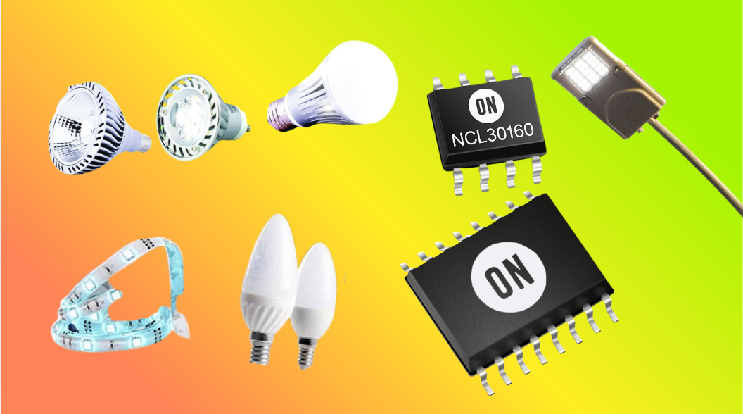
LED Driver IC: A Comprehensive Overview
An LED driver IC is an integrated circuit specifically designed to regulate the power supplied to light-emitting diodes (LEDs), ensuring they operate within safe and optimal electrical parameters. Unlike traditional light sources, LEDs are current-dependent devices, making precise current and voltag...
-
2025 / 08 / 18
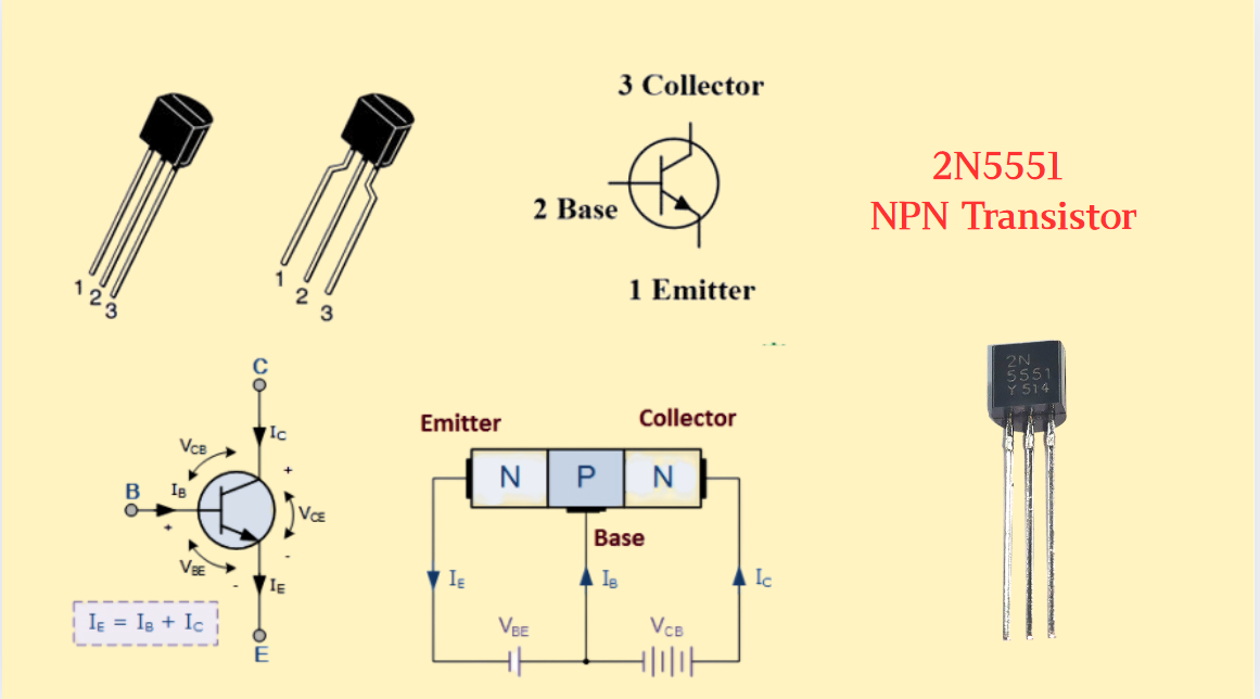
2N5551 NPN Transistor:Features,Applications,Datasheet and Pinout
In the vast realm of electronics, transistors serve as the unsung heroes, powering countless devices and circuits that have become an integral part of our daily lives. Among them, the 2N5551 NPN transistor stands out as a versatile and widely - utilized component. With its unique combination of feat...
-
2025 / 08 / 14
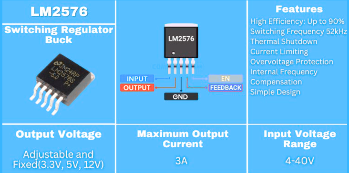
Step-Down Voltage Regulator LM2576 In-Depth Analysis: A Comprehensive Guide from Features to Applica
LM2576 is a classic step-down switching regulator introduced by Texas Instruments (TI). Since its launch, it has occupied an important position in the field of DC power conversion. With its mature technology, stable performance, and wide applicability, it has become a benchmark product in medium and...
-
2025 / 08 / 12
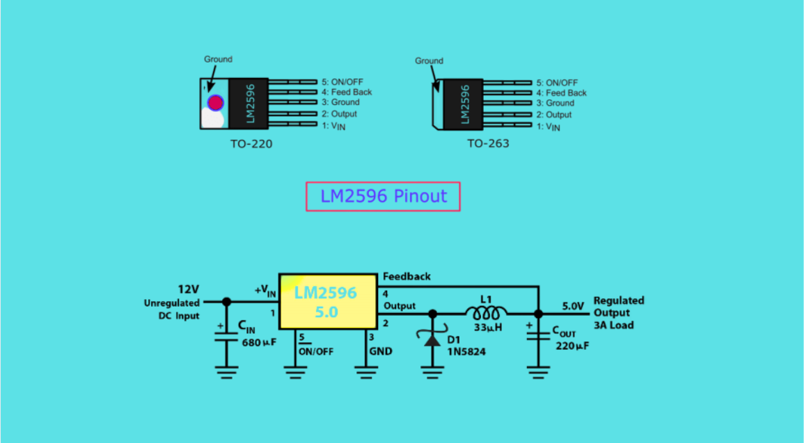
LM2596 Voltage Regulator: Replacements, Performance Traits, Internal Architecture and Practical Uses
The LM2596 series voltage regulators are monolithic integrated circuits that provide all active functions for step-down (buck) switching regulators. They can drive 3A loads with excellent line and load regulation capabilities. This series of devices includes versions with fixed output voltages of 3....
-
2025 / 08 / 07
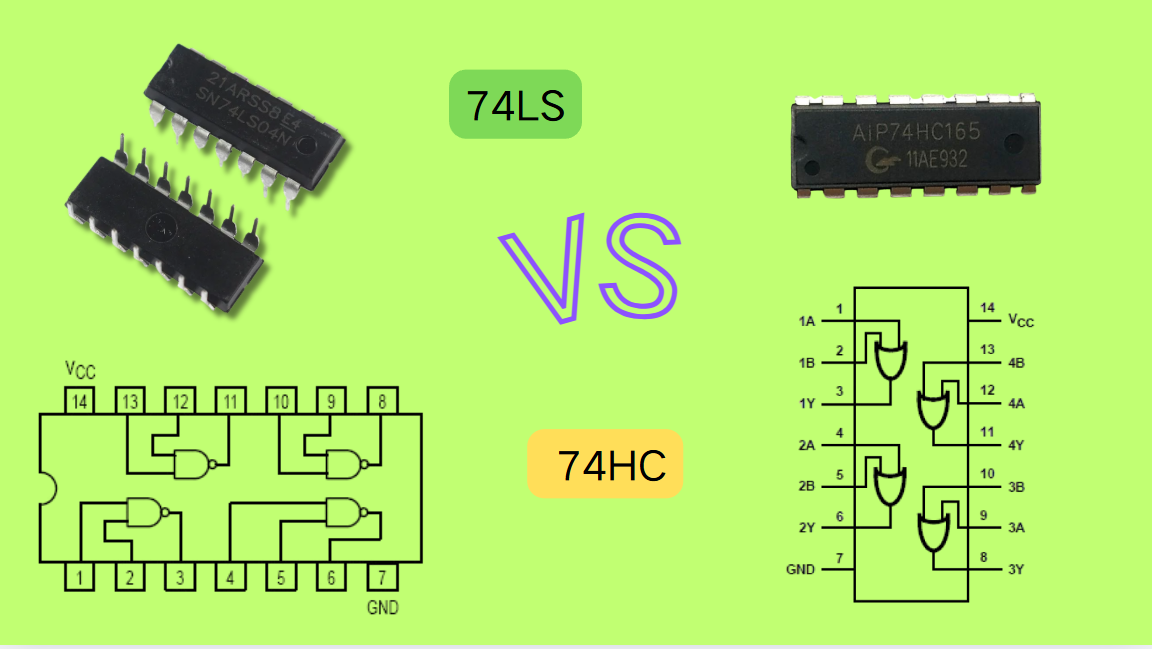
74HC vs 74LS Series ICs: A Comprehensive Comparison
The 74 series of integrated circuits (ICs) has been the backbone of digital electronics for decades, enabling the design of logic gates, flip-flops, counters, and other essential digital building blocks. Among the most popular variants are the 74HC and 74LS series, each optimized for specific applic...
-
2025 / 08 / 06
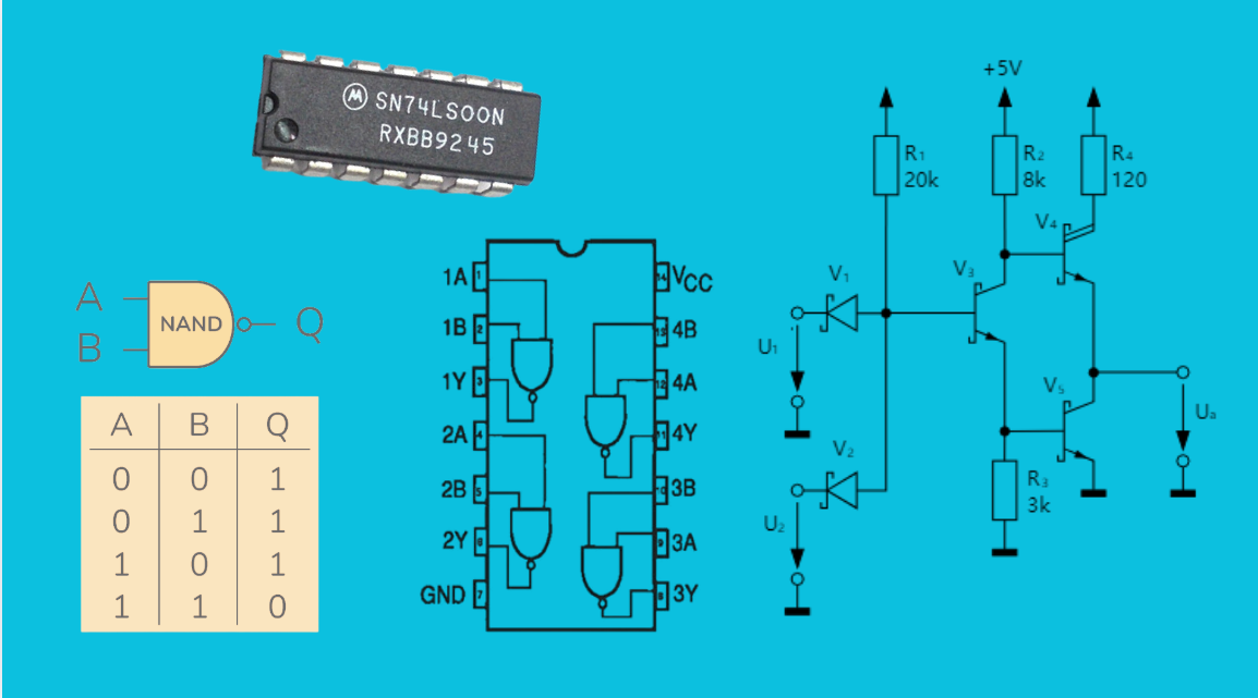
74LS00: Functions, Applications,Features and Datasheet
The 74LS00 is a widely used TTL (Transistor-Transistor Logic) integrated circuit that functions as a quad 2-input NAND gate. This means it contains four independent NAND gates, each with two input pins and one output pin. Each NAND gate in the 74LS00 performs the "NAND" logical operation: the output...
-
2025 / 08 / 01
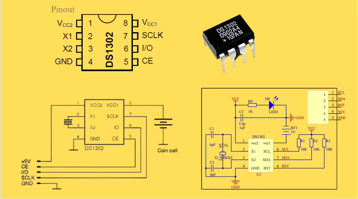
DS1302 RTC: Datasheet,Attributes,Features,Applications
As a low-power device widely used in electronic equipment, the DS1302 is centered on accurate real-time clock/calendar recording functions. It supports full-dimensional tracking of seconds, minutes, hours, days, weeks, months, and years, features automatic leap year compensation, and is compatible w...
-
2025 / 07 / 30
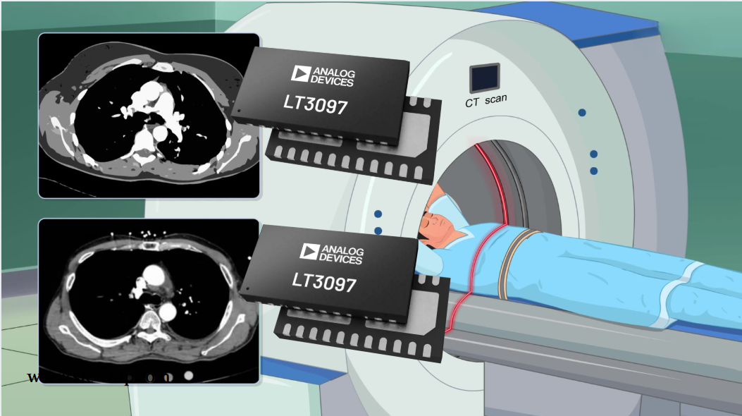
LT3097 Dual 500 mA, positive/negative, ultralow noise, ultrahigh PSRR low dropout linear regulator
The LT3097 is a dual, positive and negative, high-performance, low-dropout linear regulator featuring Analog Devices, Inc., ultralow noise and ultra-high power supply rejection ratio (PSRR) architecture for powering noise-sensitive applications. Each regulator delivers up to 500 mA with a typical 26...

2000+
Daily average RFQ Volume

30,000,000
Standard Product Unit

2800+
Worldwide Manufacturers

15,000 m2
In-stock Warehouse
 Wishlist (0 Items)