

- RFQ
- BOM
-
Contact Us
Tel: +86-0755-83501315
Email: sales@sic-components.com


- Chinese
- English
- French
- German
- Portuguese
- Spanish
- Russian
- Japanese
- Korean
- Arabic
- Irish
- Greek
- Turkish
- Italian
- Danish
- Romanian
- Indonesian
- Czech
- Afrikaans
- Swedish
- Polish
- Basque
- Catalan
- Esperanto
- Hindi
- Lao
- Albanian
- Amharic
- Armenian
- Azerbaijani
- Belarusian
- Bengali
- Bosnian
- Bulgarian
- Cebuano
- Chichewa
- Corsican
- Croatian
- Dutch
- Estonian
- Filipino
- Finnish
- Frisian
- Galician
- Georgian
- Gujarati
- Haitian
- Hausa
- Hawaiian
- Hebrew
- Hmong
- Hungarian
- Icelandic
- Igbo
- Javanese
- Kannada
- Kazakh
- Khmer
- Kurdish
- Kyrgyz
- Latin
- Latvian
- Lithuanian
- Luxembou..
- Macedonian
- Malagasy
- Malay
- Malayalam
- Maltese
- Maori
- Marathi
- Mongolian
- Burmese
- Nepali
- Norwegian
- Pashto
- Persian
- Punjabi
- Serbian
- Sesotho
- Sinhala
- Slovak
- Slovenian
- Somali
- Samoan
- Scots Gaelic
- Shona
- Sindhi
- Sundanese
- Swahili
- Tajik
- Tamil
- Telugu
- Thai
- Ukrainian
- Urdu
- Uzbek
- Vietnamese
- Welsh
- Xhosa
- Yiddish
- Yoruba
- Zulu
- Kinyarwanda
- Tatar
- Oriya
- Turkmen
- Uyghur
What is a Zero Drift Amplifier?
In the realm of precision analog electronics, maintaining accuracy over time and environmental changes is paramount. Traditional operational amplifiers (op-amps) often suffer from performance degradation due to drift—slow, unintended changes in output voltage caused by temperature variations, aging, or power supply fluctuations. To address this challenge, zero drift amplifiers (also known as auto-zero or chopper-stabilized amplifiers) have emerged as a critical solution, offering exceptional stability and precision for demanding applications. This article explores zero drift amplifiers in detail, covering their working principles, key characteristics, advantages, limitations, and practical applications.
Defining Zero Drift Amplifiers
A zero drift amplifier is a specialized type of operational amplifier designed to minimize offset voltage drift and gain drift—two primary sources of error in precision circuits. Offset voltage drift refers to the slow change in an amplifier’s input offset voltage (Vos) over time or temperature, while gain drift describes the variation in gain with environmental conditions.
Unlike conventional op-amps, which may exhibit drift values of 1–10 µV/°C, zero drift amplifiers achieve drift specifications as low as 0.01 µV/°C, making them ideal for applications requiring long-term accuracy, such as sensor interfaces, medical devices, and precision measurement systems.
How Zero Drift Amplifiers Work: Core Principles
Zero drift amplifiers eliminate drift through active compensation techniques. The two most common approaches are chopper stabilization and auto-zeroing, though modern designs often combine elements of both.
1. Chopper Stabilization
Chopper stabilization uses a high-frequency switching (chopping) mechanism to "modulate" the input signal, separate it from drift-related errors, and then "demodulate" it to recover a clean output. Here’s a step-by-step breakdown:
Modulation: The input signal is rapidly switched (chopped) at a high frequency (typically 10–100 kHz) using MOSFET switches. This converts the DC or low-frequency input signal into an AC signal centered at the chopping frequency.
Amplification: The AC signal is amplified by a high-gain, but potentially drifty, main amplifier. Since drift and offset errors are DC or low-frequency, they remain unmodulated.
Demodulation: The amplified AC signal is "chopped" again (demodulated) using a synchronized switch, converting it back to a DC signal. Drift and offset errors, which were not modulated, are rejected during this process.
Filtering: A low-pass filter removes residual chopping frequency components, leaving a clean output signal with minimal drift.
This technique effectively separates the desired signal from drift-related errors, as drift is not affected by the high-frequency chopping.
2. Auto-Zeroing
Auto-zeroing amplifiers periodically calibrate themselves to cancel offset and drift. The process occurs in two phases:
Signal Phase: The amplifier operates normally, amplifying the input signal. During this phase, a capacitor stores the offset voltage of the main amplifier.
Calibration Phase: The input is disconnected, and the amplifier’s input is shorted (or connected to a reference). The amplifier measures its own offset voltage, stores this value in a capacitor, and subtracts it from the output during the next signal phase.
This calibration repeats at a high frequency (e.g., 1 kHz to 100 kHz), continuously canceling offset and drift. Unlike chopper stabilization, auto-zeroing introduces minimal noise at the chopping frequency but may cause small glitches during calibration.
3. Hybrid Designs
Modern zero drift amplifiers often combine chopper stabilization and auto-zeroing to optimize performance. For example, a chopper-stabilized front end handles low-frequency signals and drift, while auto-zeroing corrects residual errors, achieving ultra-low drift and low noise.
Key Characteristics of Zero Drift Amplifiers
1. Ultra-Low Offset Voltage and Drift
Offset Voltage (Vos): Typically 1 µV or lower (compared to 10–100 µV for conventional op-amps).
Offset Drift: As low as 0.01 µV/°C, ensuring minimal error over temperature ranges from -40°C to 125°C.
2. Low Noise Performance
While chopper-stabilized amplifiers introduce small amounts of switching noise (at the chopping frequency), modern designs minimize this with advanced filtering. Auto-zeroing amplifiers may exhibit 1/f noise (flicker noise) at very low frequencies, but this is often negligible for most applications.
3. High Common-Mode Rejection Ratio (CMRR)
Zero drift amplifiers achieve high CMRR (typically 120 dB or higher), rejecting noise from common-mode signals (e.g., power supply fluctuations or electromagnetic interference).
4. Wide Supply Voltage Range
They operate over a broad range of supply voltages, from 1.8V (for portable devices) to 36V (for industrial systems), making them versatile for diverse applications.
5. Bandwidth Limitations
Zero drift amplifiers are optimized for low-frequency signals (DC to tens of kHz). Their bandwidth is limited by the chopping or auto-zeroing frequency, as higher frequencies may alias with the switching signal.
Advantages of Zero Drift Amplifiers
Unmatched Precision: Eliminates drift-related errors, ensuring long-term accuracy in critical applications.
Temperature Stability: Performs reliably across extreme temperature ranges, making them suitable for industrial and automotive environments.
Simplified Calibration: Reduces or eliminates the need for manual trimming or calibration in production, lowering manufacturing costs.
Robustness to Aging: Minimizes performance degradation over time, extending the lifespan of precision systems.
Compatibility with Low-Level Signals: Ideal for amplifying weak signals from sensors (e.g., thermistors, strain gauges, or pressure transducers) where even small drift would corrupt data.
Limitations and Considerations
Limited Bandwidth: Not suitable for high-frequency signals (above 100 kHz) due to chopping/auto-zeroing artifacts.
Switching Noise: Chopper-stabilized amplifiers generate noise at the chopping frequency, which may require additional filtering in sensitive applications (e.g., audio).
Power Consumption: Higher than conventional op-amps due to the active compensation circuitry, though low-power variants (e.g., <1 mW) are available for battery-powered devices.
Cost: More expensive than standard op-amps, making them impractical for non-precision applications.
Applications of Zero Drift Amplifiers
Zero drift amplifiers excel in scenarios where precision and stability are critical. Key applications include:
1. Sensor Interfaces
Strain Gauges: Measure 微小的 resistance changes in structural materials, requiring ultra-low drift to detect minute forces.
Thermocouples and RTDs: Amplify small temperature-dependent voltages (µV-level) without drift-induced errors.
Pressure Sensors: Ensure accurate measurement of low-pressure differentials in medical or industrial systems.
2. Medical Devices
ECG/EKG Machines: Amplify weak cardiac signals (mV-level) over long monitoring periods without drift corrupting data.
Blood Glucose Monitors: Precisely measure tiny currents from chemical reactions, where drift would lead to inaccurate readings.
Infusion Pumps: Maintain precise flow rates through stable control loops, critical for patient safety.
3. Precision Measurement Systems
Digital Multimeters (DMMs): Achieve high accuracy in DC voltage/current measurements, even over extended use.
Calibration Equipment: Provide stable reference signals for calibrating other instruments.
Data Acquisition Systems: Ensure low-error conversion of analog signals to digital for scientific or industrial monitoring.
4. Industrial Automation
Process Control: Maintain stable feedback loops in chemical, pharmaceutical, or manufacturing processes, where drift could cause costly errors.
Load Cells: Measure weight or force with high precision in scales or material handling systems.
5. Energy and Power Systems
Battery Management Systems: Monitor cell voltages in energy storage systems with minimal drift, ensuring safe and efficient operation.
Power Meters: Measure small power losses in electrical grids, where accuracy directly impacts efficiency calculations.
Popular Zero Drift Amplifier Models
Leading manufacturers offer a range of zero drift amplifiers tailored to specific applications:
Texas Instruments OPA388: A low-power chopper-stabilized op-amp with 0.02 µV/°C drift, ideal for portable sensors.
https://www.sic-components.com/product/search?search=OPA388
Analog Devices AD8551: An auto-zeroing op-amp with 0.005 µV/°C drift and high CMRR, suitable for precision instrumentation.
https://www.sic-components.com/product/search?search=+AD8551
Microchip MCP6V0x: Low-voltage zero drift amplifiers (1.8V to 5.5V) with 1 µV offset, designed for battery-powered devices.
https://www.sic-components.com/product/search?search=MCP6V0x
Maxim MAX9632: A high-speed (1 MHz) zero drift op-amp, balancing precision and bandwidth for mid-frequency applications.
https://www.sic-components.com/product/search?search=MAX9632
Conclusion
Zero drift amplifiers represent a significant advancement in analog circuit design, addressing the critical challenge of drift in precision systems. By leveraging chopper stabilization, auto-zeroing, or hybrid techniques, they achieve unparalleled stability, making them indispensable for applications where accuracy cannot be compromised. While they have limitations in bandwidth and cost, their benefits far outweigh these drawbacks in scenarios requiring long-term precision—from medical diagnostics to industrial process control. As technology advances, zero drift amplifiers will continue to evolve, enabling even more precise and reliable electronic systems.
https://www.sic-components.com/amplifierscategory-1

Hot Products
View More-
CR5410-50 CR Magnetics Inc.
-
HAIS 200-P LEM USA Inc.
-
CR4180-10 CR Magnetics Inc.
-
SI8519-C-IS Skyworks Solutions Inc.
-
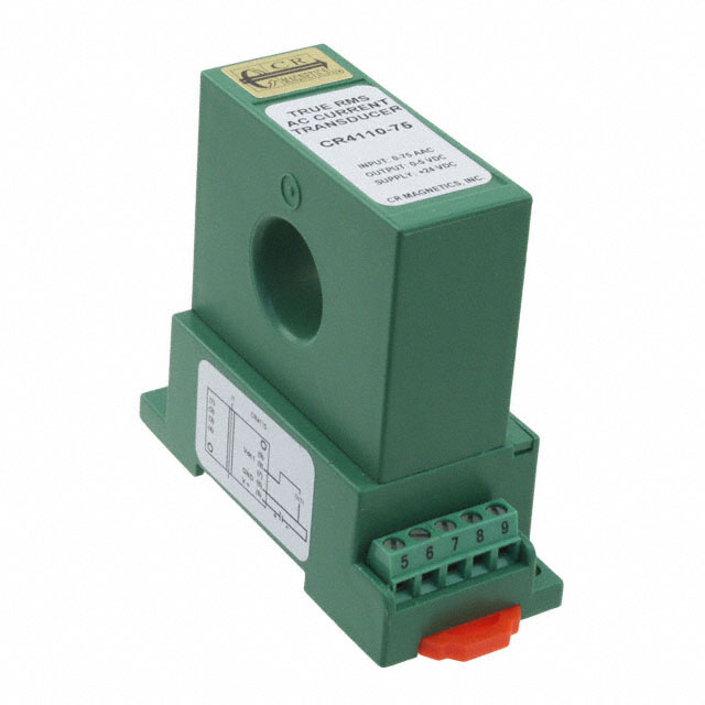
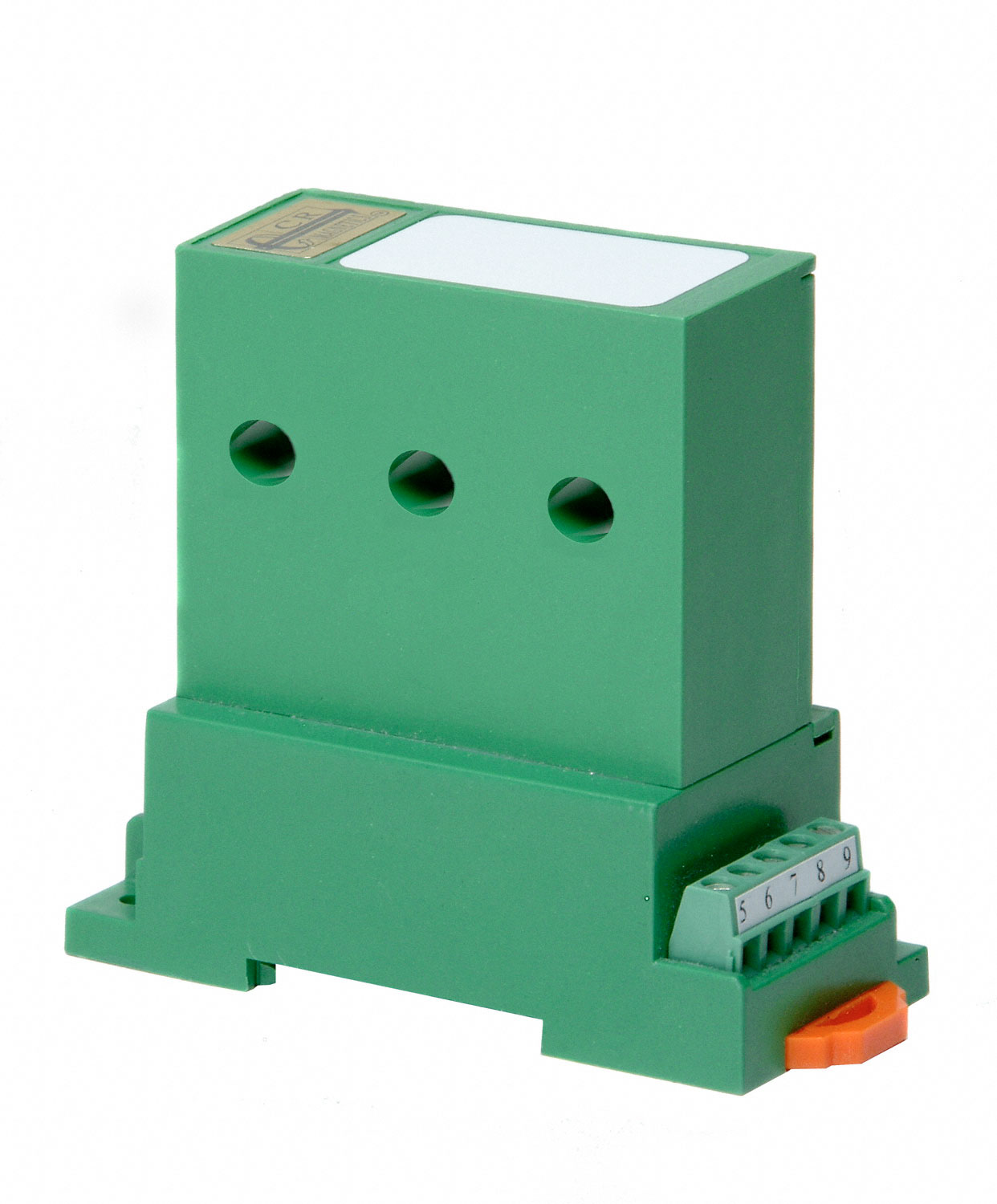
CR4110-75 CR Magnetics Inc.
-
ACS755LCB-100-PFF Allegro MicroSystems
-

CASR 6-NP/SP1 LEM USA Inc.
-
APR 400 B420L LEM USA Inc.
-
CSLW6B5 Honeywell Sensing and Productivity Solutions
-

ACS713ELCTR-30A-T Allegro MicroSystems
-
CR4210-70 CR Magnetics Inc.
-

CO-04-SF CTS Electrocomponents
Related Blogs
-
2025 / 07 / 09
CD4007: A Comprehensive Analysis of a Multifunctional CMOS Integrated Circuit
In the field of modern electronic technology, CMOS (Complementary Metal-Oxide-Semiconductor) integrated circuits have become core components in digital and analog circuit design due to their low power consumption, high integration, and excellent compatibility. As a classic CMOS device, the CD4007 oc...

-
2025 / 07 / 07
Understanding IC 7408: A Fundamental Component in Digital Logic Design
In the vast and intricate realm of digital electronics, integrated circuits (ICs) serve as the building blocks that enable the creation of complex and powerful systems. Among these, the IC 7408 holds a special place as a fundamental component in digital logic design. This article aims to provide a c...
-
2025 / 07 / 04
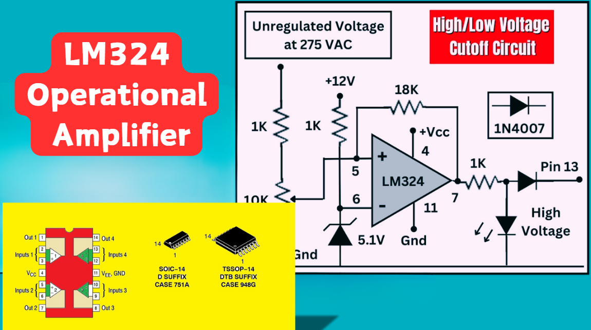
LM324 Operational Amplifier Comprehensive Guide: Pins, Applications, Packaging, and Datasheet
The LM324 is a low-cost integrated circuit featuring four independent operational amplifiers (op-amps), renowned for its wide voltage adaptability, low power consumption, and high reliability in industrial and consumer electronics. With a single-supply voltage range of 3V to 32V (or dual-supply rang...
-
2025 / 07 / 02
A Comprehensive Guide to Replacing Opto-Couplers with Digital Isolators: From Principles to Practice
In the ever-evolving landscape of electronic design, the transition from opto-couplers to digital isolators marks a pivotal shift in isolation technology. For decades, opto-couplers have been the cornerstone of electrical isolation in industrial control, medical devices, and power systems, relying o...
-
2025 / 06 / 30
Multivariate Application Analysis of Power Amplifiers in Sensor Testing
In the field of modern sensor testing, power amplifiers (PAs) serve as core components and play an indispensable role. From amplifying weak signals to simulating complex physical environments, power amplifiers provide solid guarantees for the precise testing of sensor performance through their uniqu...
-
2025 / 06 / 28
ESP32 vs STM32: Which Microcontroller Suits You Better?
In the field of embedded development, both ESP32 and STM32 are highly favored microcontrollers, each with unique features and advantages. When facing project development, how do you choose between them? This requires comprehensive consideration of multiple factors. The following detailed comparison ...
-
2025 / 06 / 26
Key Strategies to Enhance Buck Power Supply Efficiency
Improving the efficiency of Buck (step-down) switching power supplies requires a multi-dimensional approach targeting energy loss sources, including component selection, topology optimization, control strategies, and thermal management. Below are core strategies and engineering practices:...
-
2025 / 06 / 26
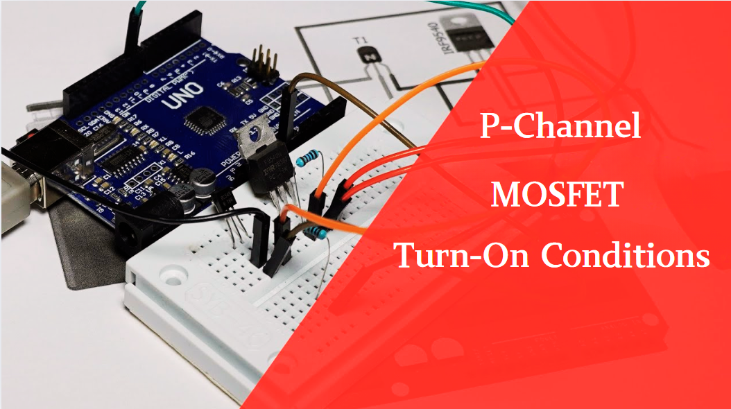
P-Channel MOSFET Turn-On Conditions
The turn-on conditions for a P-channel MOSFET (PMOS) are inverse to those of an N-channel MOSFET (NMOS), primarily governed by the relationship between the gate-source voltage (VGS) and the threshold voltage (Vth), along with voltage polarity. Here are the key points:A PMOS turns on when its gate vo...
-
2025 / 06 / 24
A8304SESTR-T Allegro MicroSystems-Single LNB Supply and Control Voltage Regulator
The Allegro MicroSystems A8304SESTR-T is a single-channel Low Noise Block Regulator (LNBR). It integrates a monolithic boost converter with MOSFET, current sensing, and compensation. Featuring a 704 kHz switching frequency, it uses few external components. With an I²C-compatible interface, it offers...
-
2025 / 06 / 20
EG25GGC-128-SGNS by Quectel Wireless Solutions Co., Ltd: Features,Symbol,Footprint and Datasheet
The Quectel EG25GGC - 128 - SGNS is an LTE Cat 4 module optimized for M2M and IoT. Supporting 3GPP Rel. 11, it offers up to 150Mbps downlink and 50Mbps uplink. With global LTE/UMTS/GSM coverage, it's backward - compatible with EDGE/GPRS. Featuring multi - constellation GNSS (GPS, GLONASS, BeiDou, et...


2000+
Daily average RFQ Volume

30,000,000
Standard Product Unit

2800+
Worldwide Manufacturers

15,000 m2
In-stock Warehouse
 Wishlist (0 Items)