

- RFQ
- BOM
-
Contact Us
Tel: +86-0755-83501315
Email: sales@sic-components.com


- Chinese
- English
- French
- German
- Portuguese
- Spanish
- Russian
- Japanese
- Korean
- Arabic
- Irish
- Greek
- Turkish
- Italian
- Danish
- Romanian
- Indonesian
- Czech
- Afrikaans
- Swedish
- Polish
- Basque
- Catalan
- Esperanto
- Hindi
- Lao
- Albanian
- Amharic
- Armenian
- Azerbaijani
- Belarusian
- Bengali
- Bosnian
- Bulgarian
- Cebuano
- Chichewa
- Corsican
- Croatian
- Dutch
- Estonian
- Filipino
- Finnish
- Frisian
- Galician
- Georgian
- Gujarati
- Haitian
- Hausa
- Hawaiian
- Hebrew
- Hmong
- Hungarian
- Icelandic
- Igbo
- Javanese
- Kannada
- Kazakh
- Khmer
- Kurdish
- Kyrgyz
- Latin
- Latvian
- Lithuanian
- Luxembou..
- Macedonian
- Malagasy
- Malay
- Malayalam
- Maltese
- Maori
- Marathi
- Mongolian
- Burmese
- Nepali
- Norwegian
- Pashto
- Persian
- Punjabi
- Serbian
- Sesotho
- Sinhala
- Slovak
- Slovenian
- Somali
- Samoan
- Scots Gaelic
- Shona
- Sindhi
- Sundanese
- Swahili
- Tajik
- Tamil
- Telugu
- Thai
- Ukrainian
- Urdu
- Uzbek
- Vietnamese
- Welsh
- Xhosa
- Yiddish
- Yoruba
- Zulu
- Kinyarwanda
- Tatar
- Oriya
- Turkmen
- Uyghur
What is filter IC?
A filter circuit is an electrical circuit that acts as a frequency - selective device. Its core function is to selectively allow certain frequencies of an electrical signal to pass through while blocking or attenuating others. In essence, it functions as a gatekeeper for different frequencies, ensuring that only the desired frequencies reach the output of the circuit.
For example, in a rectifier circuit, a filter circuit is employed to eliminate the alternating - current (AC) components from the rectified output. After rectification, the output contains both direct - current (DC) and residual AC components. The filter circuit enables the DC components to reach the load while effectively removing the unwanted AC components. An LC filter circuit, which consists of an inductor (L) and a capacitor (C), is a common type. The inductor allows DC to pass while blocking AC, and the capacitor allows AC to pass while blocking DC. By appropriately combining these components, the AC part of the rectified wave can be filtered out, resulting in a cleaner DC output.
Why Do We Need Filters?
Noise Reduction: In many electrical systems, unwanted noise or interference can corrupt the signal. For instance, in audio processing systems, electrical noise can introduce hissing or buzzing sounds. Filters are used to remove such noise, ensuring that the signal is clean. In communication systems, noise can distort the transmitted information, and filters play a crucial role in maintaining the integrity of the signal by eliminating the noise components.
Signal Smoothing: In power supply systems, the output of a rectifier is often not a pure DC but has fluctuations or ripples. Filters are used to smooth out these ripples, providing a more stable and continuous DC output. This is essential for the proper functioning of electronic devices that require a steady power supply. For example, a computer's power supply unit uses filters to ensure that the power delivered to the motherboard and other components is free from significant voltage variations.
Frequency Selection: In audio systems, different speakers (woofers, mid - range speakers, and tweeters) are designed to handle specific frequency ranges. Filters, in the form of crossover networks, are used to direct the appropriate frequencies to each speaker. This allows for a more accurate reproduction of sound, as each speaker can operate within its optimal frequency range. In radio receivers, filters enable the receiver to "tune in" to a specific radio station by selecting the desired frequency and rejecting other frequencies present in the airwaves.
Components of a Filter Circuit
Resistor (R): A resistor's main function in a filter circuit is to control the current flow. It is often used in combination with capacitors to set the time constants of the circuit. The time constant (τ) of an RC (resistor - capacitor) circuit, for example, is given by τ = RC. This time constant determines how quickly the capacitor charges and discharges, which in turn affects the frequency response of the filter. The symbol for a resistor is a zig - zag line.
Capacitor (C): Capacitors store and release electrical energy in an electric field. In filter circuits, they are used to block DC signals while allowing AC signals to pass. The ability of a capacitor to pass AC depends on its capacitance value and the frequency of the AC signal. The reactance (Xc) of a capacitor is given by Xc = 1/(2πfC), where f is the frequency of the AC signal and C is the capacitance. As the frequency increases, the reactance of the capacitor decreases, allowing more AC current to flow. The symbol for a capacitor consists of two parallel lines.
Inductor (L): Inductors store energy in a magnetic field and oppose changes in current. In filter circuits, they are used to block high - frequency signals and allow low - frequency signals to pass. The reactance (XL) of an inductor is given by XL = 2πfL, where f is the frequency of the signal and L is the inductance. As the frequency increases, the reactance of the inductor increases, making it more difficult for high - frequency signals to pass through. The symbol for an inductor is a coil - like shape.
Filter Design Techniques
Component Value Calculation: To design a filter, the first step is to calculate the values of the resistors, capacitors, and inductors. This calculation is based on the desired cutoff frequencies, bandwidths, and filter orders. For example, in a simple RC low - pass filter, the cutoff frequency (fc) is given by fc = 1/(2πRC). By choosing appropriate values of R and C, the designer can achieve the desired cutoff frequency. For more complex filters, such as multi - stage filters or filters with specific attenuation requirements, more elaborate formulas and design procedures are used.
Simulation Tools: Circuit simulation tools like SPICE (Simulation Program with Integrated Circuit Emphasis) are invaluable in filter design. These tools allow designers to model the filter circuit and simulate its behavior under different input conditions. By running simulations, designers can validate the filter design, check for any potential problems such as instability or incorrect frequency response, and optimize the design before building a physical prototype.
Component Tolerances: In real - world applications, components have manufacturing tolerances. These tolerances can affect the performance of the filter circuit. During the design process, it is important to consider these tolerances and ensure that the filter will still meet the design specifications even with component variations. This may involve using components with tighter tolerances or designing the filter with some margin to account for the variations.
Choosing the Filter Order: The filter order determines the steepness of the filter's roll - off (the rate at which the filter attenuates frequencies outside the passband). A higher - order filter will have a steeper roll - off, but it also requires more components and may introduce more phase shift. Designers need to choose the appropriate filter order based on the application requirements, balancing factors such as the desired attenuation in the stopband, the allowable phase shift, and the complexity and cost of the circuit.
Types of Filter Circuits
Low - Pass Filter (LPF): A low - pass filter allows signals with frequencies lower than a certain cutoff frequency (fc) to pass through with minimal attenuation, while attenuating signals with frequencies higher than fc. LPFs are commonly used to remove high - frequency noise from a signal. For example, in an audio system, a low - pass filter can be used to remove high - frequency hiss from the audio signal. The cutoff frequency is a key parameter, and frequencies below it are in the passband, while frequencies above it are in the stopband. The roll - off of the filter, measured in decibels per decade (dB/decade) or decibels per octave (dB/octave), determines how quickly the filter attenuates frequencies in the stopband.
High - Pass Filter (HPF): A high - pass filter does the opposite of a low - pass filter. It allows signals with frequencies higher than the cutoff frequency to pass through while attenuating signals with lower frequencies. HPFs are useful for removing DC offsets or low - frequency noise from a signal. In a guitar amplifier, for example, a high - pass filter can be used to eliminate the rumble caused by low - frequency vibrations. Similar to the LPF, the cutoff frequency and roll - off are important characteristics of the high - pass filter.
Band - Pass Filter (BPF): A band - pass filter allows a specific range of frequencies (the passband) to pass through while attenuating frequencies outside this range. The passband is defined by a lower cutoff frequency (f1) and an upper cutoff frequency (f2). The center frequency (f0) of the band - pass filter is often calculated as the geometric mean of f1 and f2, i.e., f0 = √(f1×f2). The bandwidth (BW) of the filter is given by BW = f2 - f1. Band - pass filters are used in applications where only a specific frequency band is of interest, such as in radio receivers to select a particular radio station's frequency.
Band - Stop Filter (BSF) or Notch filter: A band - stop filter blocks a specific range of frequencies (the stopband) and allows frequencies outside this range to pass through. A notch filter is a type of band - stop filter with a very narrow stopband. These filters are used to eliminate specific unwanted frequencies from a signal. For example, in power supply systems, a notch filter can be used to remove 50 Hz or 60 Hz hum, which is a common source of interference. The center frequency and bandwidth are important parameters for band - stop filters, similar to band - pass filters.
Digital Signal Processing Filter
In digital signal processing, a digital filter uses a digital processor (such as a specialized Digital Signal Processor - DSP chip or a general - purpose computer) to compute numerical values based on the sampled values of the input signal. First, the analog input signal is sampled and digitized using an Analog - to - Digital Converter (ADC). The resulting binary numbers represent the sampled values of the input signal.
The digital processor then performs numerical calculations on these input values. Typically, these calculations involve multiplying the input numbers by constants and adding the products together. The result of these calculations is the sampled values of the filtered signal. If necessary, the filtered signal is then converted back to an analog form using a Digital - to - Analog Converter (DAC).
Digital filters offer several advantages over analog filters. They can be easily programmed to implement different filter characteristics, have high precision, and are less affected by component tolerances. Additionally, digital filters can be updated or modified by changing the software program, providing great flexibility in signal processing applications.
Characteristics of Filter Circuit
Attenuation: Attenuation refers to the reduction in the amplitude of the signal at certain frequencies. Different types and orders of filters have different attenuation slopes in the stopband. A steeper attenuation slope means that the filter can more effectively block frequencies outside the passband. However, steeper slopes may also introduce ringing or oscillations in the transient response of the filter, which can distort the signal.
Phase Shift: Filter circuits introduce a phase shift in the output signal, causing the output wave to be delayed relative to the input wave. This phase shift is frequency - dependent, which means that different frequencies in the input signal will be delayed by different amounts. In some applications, such as in audio systems or communication systems, excessive phase shift can lead to signal distortion or interference, affecting the overall quality of the signal.
Order: The order of a filter is related to the number of reactive components (capacitors and inductors) used in the filter design. Higher - order filters have steeper roll - offs, which allow for a more rapid transition between the passband and the stopband. However, higher - order filters also require more components, which can increase the complexity and cost of the circuit. Additionally, higher - order filters tend to introduce larger phase shifts, which may need to be considered in the design process.
Advantages of Filter Circuit
Accurate Signal Control: Filter circuits enable precise control over the frequencies present in a signal. By selectively passing or blocking specific frequencies, they can enhance the clarity and definition of the signal. In audio processing, for example, filters can be used to emphasize certain frequency ranges, such as the bass or treble, while reducing unwanted noise or frequencies that may distort the sound.
Enhanced Performance: Filters improve the performance of various systems by removing unwanted frequencies. In power supply systems, filters eliminate AC ripple, resulting in a smoother DC output. This, in turn, improves the performance of the devices connected to the power supply, reducing the risk of malfunctions or premature failure. In communication systems, filters help in selecting the desired signal and rejecting interference, ensuring reliable data transmission.
Signal Enhancement: They can enhance specific frequency components of a signal, thereby improving the overall quality of the signal. For example, in image processing, filters can be used to enhance edges or details in an image by selectively amplifying the relevant frequency components.
Customization: Filters can be designed and adjusted to meet the specific requirements of different applications. Designers can choose the type of filter, its cutoff frequencies, bandwidth, and order based on the needs of the system. This flexibility allows for the optimization of the filter performance for a wide range of applications.
Wide Range of Applications: Filter circuits are used in numerous industries, including digital signal processing, audio, radio, telecommunications, and power electronics. Their versatility makes them essential components in modern electronic systems, enabling the proper functioning of a vast array of devices and equipment.
Disadvantages of Filter Circuit
Component Tolerance: Due to manufacturing tolerances, the values of components such as resistors, capacitors, and inductors may vary slightly from their nominal values. These variations can affect the performance of the filter circuit, leading to deviations in the cutoff frequencies, attenuation characteristics, or overall frequency response. In some cases, this may require additional calibration or adjustment of the filter to meet the desired specifications.
Complex Circuitry for Advanced Filters: Filters with multiple bands or sharp cut - off frequencies often require more complex circuitry. Designing and implementing such advanced filters can be challenging and time - consuming. The increased complexity also leads to higher costs, as more components and potentially more sophisticated manufacturing processes may be required.
Nonlinearities in Active Filters: Active filters, which use operational amplifiers or other active components, can introduce nonlinearities into the circuit. These nonlinearities can distort the signal, especially at high signal levels or when the filter is operating near its limits. Nonlinearities may also cause intermodulation distortion, where new frequency components are generated as a result of the interaction between different input frequencies.
Power Consumption in Active Filters: Active filters typically consume more power compared to passive filters because they rely on active components such as op - amps that require a power supply. This increased power consumption can be a significant drawback in battery - powered devices or applications where power efficiency is a critical factor.
Signal Loss: Since filters are designed to attenuate certain frequencies, there is always some loss of signal in the desired frequency band. Although efforts are made to minimize this loss, in some applications where signal strength is crucial, even a small amount of loss can be a concern. For example, in long - distance communication systems, signal loss introduced by filters may need to be compensated for using amplifiers or other signal - boosting techniques.
Applications of Filter Circuits
Anti - Alias Filtering: In digital systems, aliasing occurs when a signal is sampled at a rate that is too low, causing high - frequency components to be misinterpreted as lower - frequency components. Anti - alias filters are placed before the analog - to - digital converter (ADC) to limit the bandwidth of the input signal. By removing frequencies above the Nyquist frequency (half of the sampling rate), these filters prevent aliasing and ensure accurate digital representation of the analog signal.
Noise Rejection: As mentioned earlier, filter circuits are widely used to reject noise from signals. In electronic devices such as computers, televisions, and mobile phones, filters are used to remove electrical noise that can interfere with the proper functioning of the circuits. In industrial control systems, filters are used to protect sensitive sensors and control circuits from electrical noise generated by motors, transformers, and other equipment.
Interference Rejection: In communication systems, filter circuits are used to reject interference from other signals. For example, in a radio receiver, a band - pass filter is used to select the desired radio station's frequency and reject other stations' frequencies. In wireless communication systems, filters are used to separate different frequency bands used for transmission and reception, preventing interference between different channels.
Audio Signal Processing: In audio systems, filter circuits are used for various purposes. Crossover networks in loudspeakers use filters to direct different frequency ranges to the appropriate speakers. Equalizers use filters to adjust the balance of different frequency components in an audio signal, allowing users to customize the sound according to their preferences. Filters are also used to remove noise and unwanted frequencies from audio recordings, improving the overall sound quality.
Power Supply Conditioning: In power supply systems, filters are essential for conditioning the power output. They remove AC ripple from the rectified DC output, providing a more stable and clean power supply for electronic devices. Additionally, filters can be used to suppress electromagnetic interference (EMI) generated by the power supply, preventing it from interfering with other electronic equipment.
SIC Electronics is a worldwide distributor of electronic components with high quality control. The products and industries currently involved in the company consist of military industry, automobile, medical treatment, consumer electronics, industrial control, Internet of things, new energy, communications, etc. We not only provide customers with products and service, but also offer them relevant peripheral cooperation. If you have products to sell or you are troubled with some product-related problems, please feel free to contact us. Moreover, we have our own warehouses, top-level quality control talents, senior purchasing staff, a great many of in-depth cooperation factories and contract partners of global trade logistics, and so on. We take pleasure in sharing our resources with customers, with an expectation to achieve win-win cooperation.
https://www.sic-components.com/filters


Hot Products
View More-
SX-LK15B-A Global Industrial
-

R-CF High Country Plastics
-
SX-5073-5 Global Industrial
-
B2081981 High Country Plastics
-
46895 Vollrath
-

PLEG High Country Plastics
-

WB-15AG High Country Plastics
-
K-9 Petersen Manufacturing
-
18"SORP Kane
-
B2081821 High Country Plastics
-
R-HF-BK High Country Plastics
-
SX-5073-3A Global Industrial
Related Blogs
-
2025 / 07 / 19
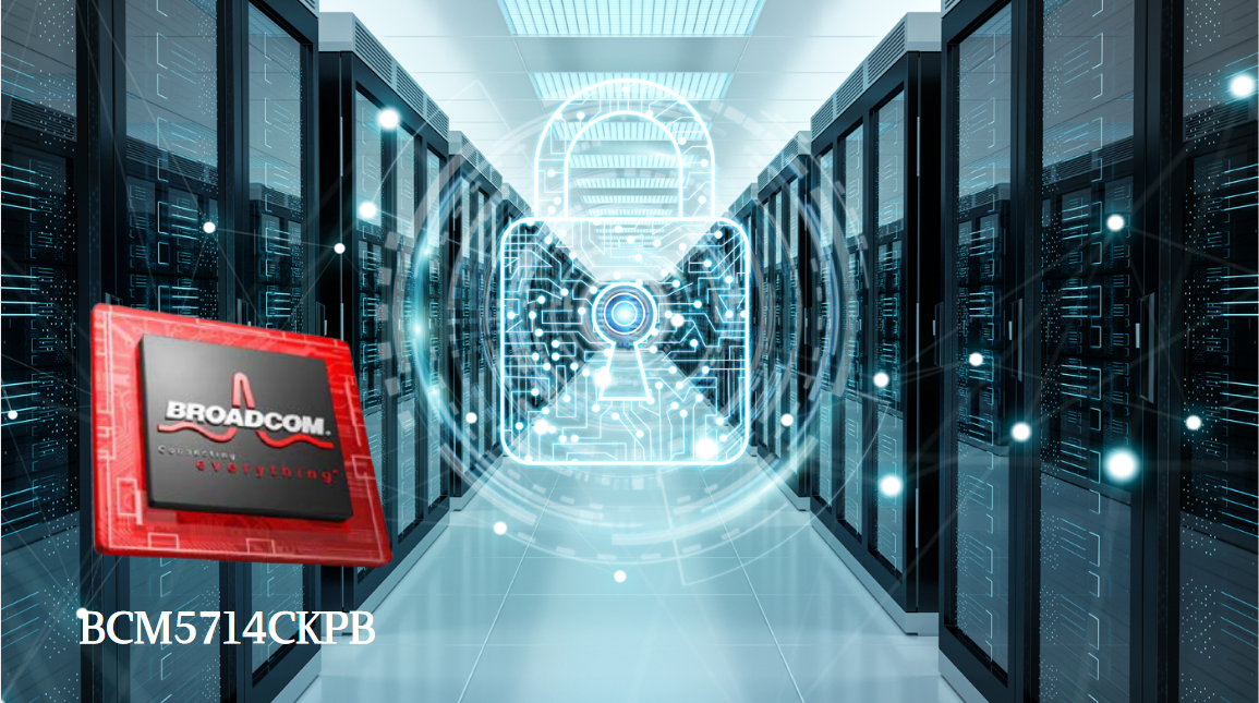
Broadcom BCM5714CKPB: Featrues,Applications,Datasheet And Advantages
When it comes to reliable, high-performance network connectivity in enterprise and industrial systems, the Broadcom BCM5714CKPB stands as a standout solution. This dual-port Gigabit Ethernet controller, developed by Broadcom—a leader in semiconductor innovation—combines robust features, versatile co...
-
2025 / 07 / 15
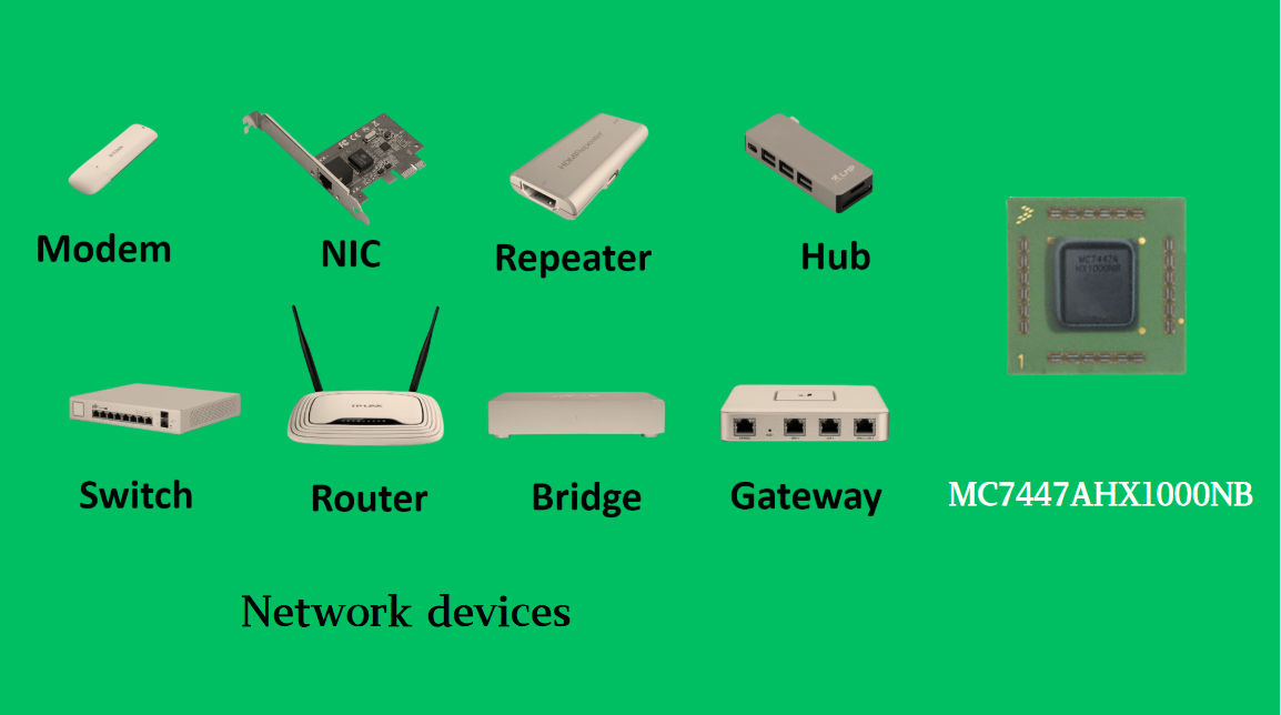
MC7447AHX1000NB: Technical Analysis and Applications of a High-Performance PowerPC Architecture Proc
In the field of embedded computing and network systems, the performance, energy efficiency, and compatibility of processors are often crucial to the success of a design. The MC7447AHX1000NB launched by NXP (formerly Freescale), as an important member of the MPC7447A series, has become an ideal choic...
-
2025 / 07 / 14
Nexperia Unveils New 1200V/20A SiC Schottky Diodes to Empower Efficient Industrial Power Innovations
Nexperia recently announced the addition of two new 1200V, 20A silicon carbide (SiC) Schottky diodes—PSC20120J and PSC20120L—to its power electronics portfolio, further expanding its product landscape in high-performance semiconductors. Specifically designed to address the increasingly stringent dem...
-
2025 / 07 / 09
CD4007: A Comprehensive Analysis of a Multifunctional CMOS Integrated Circuit
In the field of modern electronic technology, CMOS (Complementary Metal-Oxide-Semiconductor) integrated circuits have become core components in digital and analog circuit design due to their low power consumption, high integration, and excellent compatibility. As a classic CMOS device, the CD4007 oc...

-
2025 / 07 / 07
Understanding IC 7408: A Fundamental Component in Digital Logic Design
In the vast and intricate realm of digital electronics, integrated circuits (ICs) serve as the building blocks that enable the creation of complex and powerful systems. Among these, the IC 7408 holds a special place as a fundamental component in digital logic design. This article aims to provide a c...
-
2025 / 07 / 04
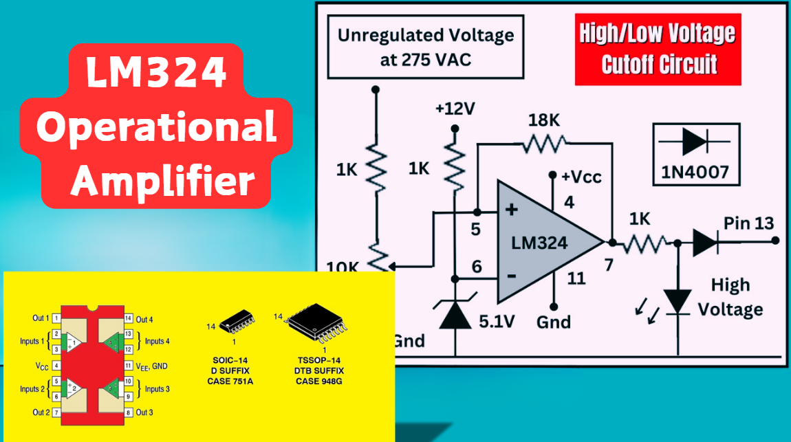
LM324 Operational Amplifier Comprehensive Guide: Pins, Applications, Packaging, and Datasheet
The LM324 is a low-cost integrated circuit featuring four independent operational amplifiers (op-amps), renowned for its wide voltage adaptability, low power consumption, and high reliability in industrial and consumer electronics. With a single-supply voltage range of 3V to 32V (or dual-supply rang...
-
2025 / 07 / 02
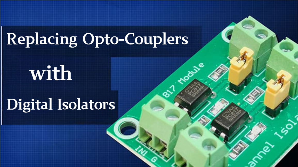
A Comprehensive Guide to Replacing Opto-Couplers with Digital Isolators: From Principles to Practice
In the ever-evolving landscape of electronic design, the transition from opto-couplers to digital isolators marks a pivotal shift in isolation technology. For decades, opto-couplers have been the cornerstone of electrical isolation in industrial control, medical devices, and power systems, relying o...
-
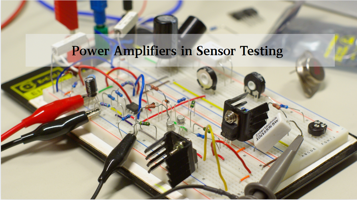
2025 / 06 / 30
Multivariate Application Analysis of Power Amplifiers in Sensor Testing
In the field of modern sensor testing, power amplifiers (PAs) serve as core components and play an indispensable role. From amplifying weak signals to simulating complex physical environments, power amplifiers provide solid guarantees for the precise testing of sensor performance through their uniqu...
-
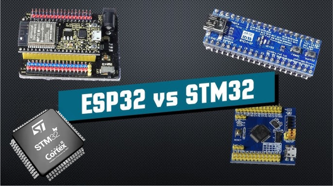
2025 / 06 / 28
ESP32 vs STM32: Which Microcontroller Suits You Better?
In the field of embedded development, both ESP32 and STM32 are highly favored microcontrollers, each with unique features and advantages. When facing project development, how do you choose between them? This requires comprehensive consideration of multiple factors. The following detailed comparison ...
-
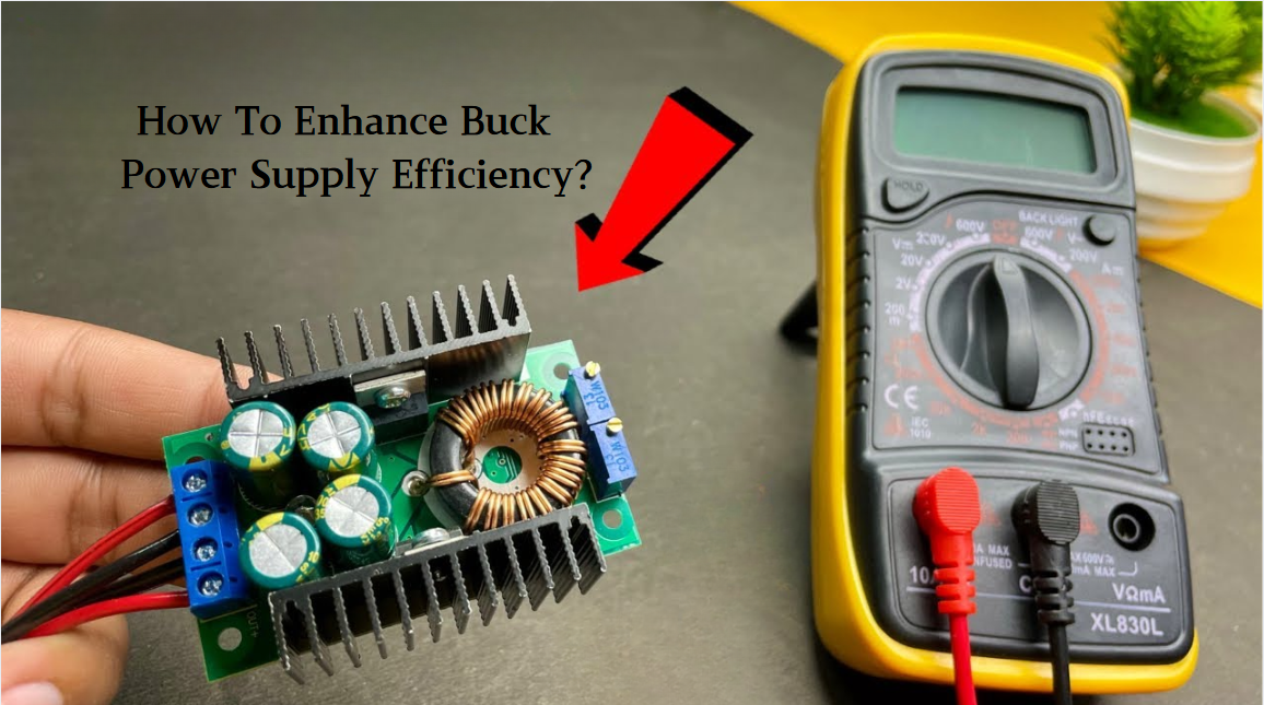
2025 / 06 / 26
Key Strategies to Enhance Buck Power Supply Efficiency
Improving the efficiency of Buck (step-down) switching power supplies requires a multi-dimensional approach targeting energy loss sources, including component selection, topology optimization, control strategies, and thermal management. Below are core strategies and engineering practices:...

2000+
Daily average RFQ Volume

30,000,000
Standard Product Unit

2800+
Worldwide Manufacturers

15,000 m2
In-stock Warehouse
 Wishlist (0 Items)