

- RFQ
- BOM
-
Contact Us
Tel: +86-0755-83501315
Email: sales@sic-components.com


- Chinese
- English
- French
- German
- Portuguese
- Spanish
- Russian
- Japanese
- Korean
- Arabic
- Irish
- Greek
- Turkish
- Italian
- Danish
- Romanian
- Indonesian
- Czech
- Afrikaans
- Swedish
- Polish
- Basque
- Catalan
- Esperanto
- Hindi
- Lao
- Albanian
- Amharic
- Armenian
- Azerbaijani
- Belarusian
- Bengali
- Bosnian
- Bulgarian
- Cebuano
- Chichewa
- Corsican
- Croatian
- Dutch
- Estonian
- Filipino
- Finnish
- Frisian
- Galician
- Georgian
- Gujarati
- Haitian
- Hausa
- Hawaiian
- Hebrew
- Hmong
- Hungarian
- Icelandic
- Igbo
- Javanese
- Kannada
- Kazakh
- Khmer
- Kurdish
- Kyrgyz
- Latin
- Latvian
- Lithuanian
- Luxembou..
- Macedonian
- Malagasy
- Malay
- Malayalam
- Maltese
- Maori
- Marathi
- Mongolian
- Burmese
- Nepali
- Norwegian
- Pashto
- Persian
- Punjabi
- Serbian
- Sesotho
- Sinhala
- Slovak
- Slovenian
- Somali
- Samoan
- Scots Gaelic
- Shona
- Sindhi
- Sundanese
- Swahili
- Tajik
- Tamil
- Telugu
- Thai
- Ukrainian
- Urdu
- Uzbek
- Vietnamese
- Welsh
- Xhosa
- Yiddish
- Yoruba
- Zulu
- Kinyarwanda
- Tatar
- Oriya
- Turkmen
- Uyghur
What is the motor driver IC?
In the realm of modern electronics, motors power countless devices, from the tiny motors in smartphones that enable camera autofocus to the large motors in industrial robots that perform complex manufacturing tasks. At the heart of effectively controlling these motors lies a crucial component: the motor driver IC. Understanding what a motor driver IC is, its functionality, and its various aspects is essential for anyone involved in electronics design, robotics, automation, or related fields.
What is the Motor Driver IC?
A motor driver IC, or motor driver integrated circuit, is an electronic chip designed to interface between a microcontroller (or other control circuitry) and an electric motor. Its primary function is to take low - power control signals from the microcontroller and convert them into the high - current, high - voltage signals required to drive the motor. In essence, it acts as a translator and amplifier, ensuring that the motor receives the appropriate power and commands to operate as intended.
The Types and Features of Motor Driver ICs
Brushed DC Motor Driver ICs
These are among the most common types. They are designed to drive brushed DC motors, which use a commutator and brushes to transfer electrical current to the motor coils. Brushed DC motor driver ICs are relatively simple in design and cost - effective. They offer basic functionality for controlling the motor's speed and direction. However, due to the mechanical nature of the brushes, they have a limited lifespan and may generate electrical noise.
Brushless DC (BLDC) Motor Driver ICs
BLDC motors are becoming increasingly popular due to their higher efficiency, longer lifespan, and quieter operation. BLDC motor driver ICs are more complex as they need to generate the appropriate waveforms to control the motor's electronic commutation. These ICs often come with advanced features such as sensorless operation, which eliminates the need for external position sensors, reducing cost and complexity. They are suitable for applications where high performance and reliability are required, like in electric vehicles and drones.
Stepper Motor Driver ICs
Stepper motors are known for their precise positioning capabilities, moving in discrete steps. Stepper motor driver ICs send out carefully timed pulses to control the motor's movement. They offer high precision and repeatability, allowing for accurate control over the motor's position and speed. Some stepper motor driver ICs support micro - stepping, which further enhances the precision by dividing each step into smaller increments.
Servo Motor Driver ICs
Servo motors are designed for applications that require quick and accurate angular positioning. Servo motor driver ICs take input signals, typically in the form of pulse - width - modulated (PWM) signals, and convert them into the appropriate power to drive the servo motor to the desired position. They provide fast response times and high accuracy, making them ideal for robotics, remote - controlled vehicles, and camera gimbals.
How Does the Motor Driver IC Work?
The motor driver IC operates by first receiving control signals from the microcontroller. These signals are usually in the form of digital logic levels (e.g., 0V for low and 5V for high). The IC then uses internal circuitry, often based on transistors or MOSFETs, to amplify these low - power signals.
For speed control, many motor driver ICs use pulse - width modulation (PWM). PWM involves rapidly switching the power to the motor on and off at a high frequency. By varying the proportion of time the power is on (the duty cycle), the average voltage applied to the motor can be adjusted, thereby controlling its speed. For direction control, the IC changes the polarity of the voltage applied to the motor coils. This is often achieved using an H - bridge circuit, which will be discussed in more detail later.
How to Make Up a Motor Driver System?
A motor driver system typically consists of several key components:
Controller: This is usually a microcontroller or microprocessor. It serves as the "brain" of the system, generating the control signals based on user input, sensor data, or programmed algorithms. For example, in a robotic arm, the microcontroller might receive position data from sensors and send commands to the motor driver IC to move the arm to the desired position.
Motor Driver IC: As described earlier, it takes the control signals from the controller and drives the motor.
Motor: This can be any type of electric motor, such as a DC, BLDC, stepper, or servo motor, depending on the application requirements.
Power Supply: It provides the electrical energy required to power both the motor driver IC and the motor. The power supply must be capable of delivering the appropriate voltage and current ratings for the system. For example, a high - power industrial motor may require a power supply with a high voltage and current capacity.
Sensors (Optional): In some systems, sensors such as encoders (for measuring motor position and speed) or current sensors (for monitoring the motor current) are used. The sensor data can be fed back to the controller, enabling closed - loop control for more precise operation.
What is an H - bridge Circuit?
The H - bridge circuit is a fundamental building block in many motor driver ICs, especially for applications that require bidirectional control of the motor. It consists of four switches (usually transistors or MOSFETs) arranged in an "H" shape, with the motor connected across the middle of the "H".
By turning on and off different combinations of these switches, the direction of current flow through the motor can be changed. For example, when the top - left and bottom - right switches are closed, current flows through the motor in one direction, causing it to rotate in one direction. When the top - right and bottom - left switches are closed, the current direction is reversed, and the motor rotates in the opposite direction. The H - bridge also enables speed control using PWM, as the switches can be rapidly toggled to vary the average voltage applied to the motor.
How to Stop the Motor (Braking)
There are several methods for stopping a motor using a motor driver IC. One common method is electrical braking, which can be achieved through the H - bridge circuit. In dynamic braking, the motor is short - circuited by closing both switches on one side of the H - bridge. This causes the motor to act as a generator, converting its kinetic energy into electrical energy, which is dissipated as heat in the motor windings, rapidly slowing down the motor.
Another method is regenerative braking, mainly used in BLDC motors. In this case, the motor driver IC redirects the energy generated by the motor during braking back to the power supply, rather than dissipating it as heat. This can improve the overall efficiency of the system, especially in applications where energy conservation is important, such as in electric vehicles.
The Role of Motor Driver IC
The motor driver IC plays a multi - faceted role in a motor control system. Firstly, it provides the necessary power amplification to drive the motor, ensuring that the motor receives sufficient current and voltage to operate. Secondly, it enables precise control over the motor's speed, direction, and torque. This is crucial for applications that require accurate positioning, smooth motion, or variable speed operation. Moreover, motor driver ICs often come with built - in protection features. These include overcurrent protection, which safeguards the motor and the IC from damage in case of excessive current draw, and overtemperature protection, which shuts down the system if the IC or motor overheats. These protection features enhance the reliability and lifespan of the motor control system.
The Applications of Motor Driver IC
Robotics: In robotic arms, legs, and other moving parts, motor driver ICs are used to control the movement of servo, stepper, and DC motors, enabling precise and coordinated motion.
Automotive: They are used in various automotive systems, such as power windows, windshield wipers, seat adjustment mechanisms, and electric vehicle drivetrains.
Consumer Electronics: In devices like smartphones, tablets, laptops, and cameras, motor driver ICs control motors for functions such as autofocus, zoom, and hard - drive spindle rotation.
Industrial Automation: In factories, motor driver ICs are used to control conveyor belts, robotic assembly lines, and other automated machinery, ensuring efficient and accurate production processes.
Home Appliances: Appliances like washing machines, dryers, refrigerators, and fans often use motor driver ICs to control the motors that drive their various components.
How to Choose the Right Motor Driver?
When choosing a motor driver IC, several factors need to be considered:
Motor Type: Different motor driver ICs are designed for specific types of motors. Ensure that the IC is compatible with the motor you intend to use.
Power Requirements: Consider the voltage and current ratings of the motor. The motor driver IC should be able to supply the necessary power without overheating or failing.
Control Requirements: If you need precise speed control, bidirectional operation, or high - precision positioning, look for an IC that offers the appropriate features, such as PWM control or support for micro - stepping.
Protection Features: Choose an IC with adequate protection features, such as overcurrent, overtemperature, and short - circuit protection, to ensure the safety and reliability of your system.
Communication Interfaces: Some motor driver ICs support communication interfaces like SPI, I2C, or CAN bus, which can be useful for advanced control and monitoring. Consider whether such interfaces are required for your application.
Motor Drivers vs. Motor Controllers
To better understand the disparities between motor drivers and motor controllers, we can organize the information into a more narrative - based comparison, as well as a visual table for quick reference. This will help to clearly showcase how each component varies across multiple aspects.
1. Functionality
Motor Driver: A motor driver acts as a crucial link between a microcontroller and a motor. Its main job is to take the low - power signals from the microcontroller and transform them into the high - current, high - voltage signals that the motor needs to operate. It's like a translator and amplifier, enabling the motor to start, stop, change directions, and adjust its speed according to basic commands from the microcontroller.
Motor Controller: In contrast, a motor controller is a more comprehensive and powerful device. It doesn't just drive the motor; it oversees every aspect of motor operation. This includes the functions of a motor driver, but also extends to complex tasks such as precise positioning, torque control, and the implementation of feedback algorithms to ensure the motor performs exactly as required.
2. Control Signals
Motor Driver: Motor drivers receive simple instructions related to the motor's direction and speed. For example, a basic on - off signal or a simple command to increase or decrease the speed is all it typically needs to function.
Motor Controller: Motor controllers, on the other hand, are designed to handle complex commands. They can receive instructions for intricate positioning tasks, control the torque applied by the motor, and work with feedback algorithms to make real - time adjustments to the motor's operation.
3. Complexity and Components
Motor Driver: Motor drivers are relatively simple in design. They mainly consist of power amplifiers and basic H - bridge circuits, which are responsible for the fundamental power amplification and direction control of the motor.
Motor Controller: Motor controllers are far more complex. They incorporate not only motor drivers but also microprocessors, feedback loops, and may even include sensors. These components work together to provide full - fledged control over the motor, enabling precise and sophisticated operation.
4. User Interaction, Feedback, and Applications
Motor Driver: With a motor driver, user interaction is minimal. Once it's set up, it simply executes the commands it receives. Feedback is often limited, usually only including basic sensing of current or voltage, if at all. This makes motor drivers suitable for simple applications like toys or basic automation systems where straightforward motor operation is sufficient.
Motor Controller: Motor controllers demand a high level of user interaction. Users need to set various parameters, configure the system, and make adjustments to ensure optimal performance. They offer advanced feedback mechanisms, providing information on the motor's position, speed, load, and potential errors. This makes them essential for sophisticated systems such as robotics and industrial automation, where precise control and monitoring are critical.
5. Cost, Programming, and Integration
Motor Driver: Motor drivers are generally less expensive due to their simpler design and fewer components. Programming them usually requires only minimal effort, and they are easy to integrate into systems with limited external components.
Motor Controller: Motor controllers, on the other hand, are more expensive because of their added functionalities and complex components. Programming them requires detailed knowledge and configuration, and integrating them into a system often involves additional modules such as sensors and communication interfaces.
Troubleshooting Motor Drivers
When issues arise with a motor driver system, several steps can be taken for troubleshooting:
Check Power Supply: Ensure that the power supply is providing the correct voltage and current. A faulty power supply can cause the motor to malfunction or the driver IC to fail.
Verify Connections: Check all the connections between the controller, motor driver IC, motor, and power supply. Loose or incorrect connections can lead to inconsistent operation or no operation at all.
Inspect for Overheating: If the motor driver IC or the motor is overheating, it could indicate a problem such as excessive current draw, a short circuit, or insufficient cooling. Check for any signs of damage or abnormal operation.
Test the Motor Separately: Isolate the motor and test it directly with a suitable power source to determine if the problem lies with the motor itself. If the motor works fine on its own, the issue is likely with the motor driver IC or the control circuitry.
Check for Faulty Components: Use a multimeter to test the transistors, MOSFETs, or other components within the motor driver IC for any signs of failure.
Latest Developments in Motor Driver Technology
The field of motor driver technology is constantly evolving. One of the latest trends is the integration of more advanced features into a single IC. For example, some modern motor driver ICs now include built - in sensors for current, voltage, and temperature monitoring, eliminating the need for external sensors in some applications.
Another development is the improvement in energy efficiency. Newer motor driver ICs are designed to reduce power losses, which is especially important in battery - powered applications like electric vehicles and portable electronics. Additionally, advancements in semiconductor technology have led to smaller, more powerful motor driver ICs, enabling more compact and efficient motor control systems.
SIC Electronic Components (Shenzhen) Co., Ltd. has now developed into a well - known domestic IC hybrid (authorized and non - authorized) electronic component distributor in China. Over the years, the company has won a good reputation in the industry with its good credit, reliable quality, competitive prices, fast logistics, and flexible financial support. It has now become a well - known enterprise in the electronic component industry. It has established stable business relationships with AMD as well as component developers from Hong Kong and Taiwan, and enjoys the franchise distribution rights of components from many companies. Here are some recommended Motor Driver IC for you:
STSPIN32G0A1 https://www.sic-components.com/product/product?product_id=7702467
Manufacturer: STMicroelectronics
Features: A 45V brushless DC motor driver IC, suitable for three-phase brushless DC motors. The input voltage is 6.7 - 45V, the output current is 16 - 18mA, and it is packaged in a surface mount package.
DRV2603RUNR https://www.sic-components.com/product/product?product_id=3487230
Manufacturer: Texas Instruments
Features: It is an IC motor driver with an operating voltage range of 2.5V - 5.2V and is packaged in a 10 - WQFN package. It can be used for haptic feedback. It has a fully integrated drive, control, and power stage, adopting Power MOSFET technology. It is controlled via Parallel and PWM interfaces and has a two - half - bridge output configuration.
A3901SEJTR - T https://www.sic-components.com/product/product?product_id=1108987
Manufacturer: Allegro MicroSystems
Features: It is a bipolar brushed DC motor driver chip with an operating voltage range of 2.5V - 5.5V and an output current of 400mA. It is packaged in a 10 - WFDFN Exposed Pad package. It has a fully integrated drive, control, and power stage, adopting Power MOSFET technology. It is controlled via a Parallel interface and has a four - half - bridge output configuration. The step resolution is 1 and 1/2, and it is suitable for general - purpose applications.
DRV8231ADSGR https://www.sic-components.com/product/product?product_id=15853799
Manufacturer: Texas Instruments
Features: It is a 33V H - bridge motor driver with an operating voltage range of 4.5V - 33V and an output current of 3.7A. It is packaged in an 8 - WFDFN Exposed Pad package. It has a fully integrated drive, control, and power stage, adopting NMOS technology. It is controlled via a PWM interface and has a two - half - bridge output configuration. It is suitable for applications such as printers.
DRV8231ADDAR https://www.sic-components.com/product/product?product_id=16184255
Manufacturer: Texas Instruments
Features: Similar to DRV8231ADSGR, it is a 33V H - bridge motor driver with an operating voltage range of 4.5V - 33V and an output current of 3.7A. It is packaged in an 8 - PowerSOIC package. It has a fully integrated drive, control, and power stage, adopting NMOS technology. It is controlled via a PWM interface and has a two - half - bridge output configuration. It is suitable for applications such as printers, and its operating temperature range is - 40°C - 150°C (TJ).
Hot Products
View More-

4172701XX-3 Digital View Inc.
-
4169600XX-3 Digital View Inc.
-
4173900XX-3 Digital View Inc.
-
4176401XX-3 Digital View Inc.
-
ZEDH0500D27 AZ Displays
-
4176700XX-3 Digital View Inc.
-
CR1T-02-5WN-01 A D Metro
-
4171700XX-3 Digital View Inc.
-

SC402S 3M
-
ZEDH1010L19 AZ Displays
-
4173100XX-3 Digital View Inc.
-
4169300XX-3 Digital View Inc.
Related Blogs
-
2025 / 07 / 09
CD4007: A Comprehensive Analysis of a Multifunctional CMOS Integrated Circuit
In the field of modern electronic technology, CMOS (Complementary Metal-Oxide-Semiconductor) integrated circuits have become core components in digital and analog circuit design due to their low power consumption, high integration, and excellent compatibility. As a classic CMOS device, the CD4007 oc...

-
2025 / 07 / 07
Understanding IC 7408: A Fundamental Component in Digital Logic Design
In the vast and intricate realm of digital electronics, integrated circuits (ICs) serve as the building blocks that enable the creation of complex and powerful systems. Among these, the IC 7408 holds a special place as a fundamental component in digital logic design. This article aims to provide a c...
-
2025 / 07 / 04
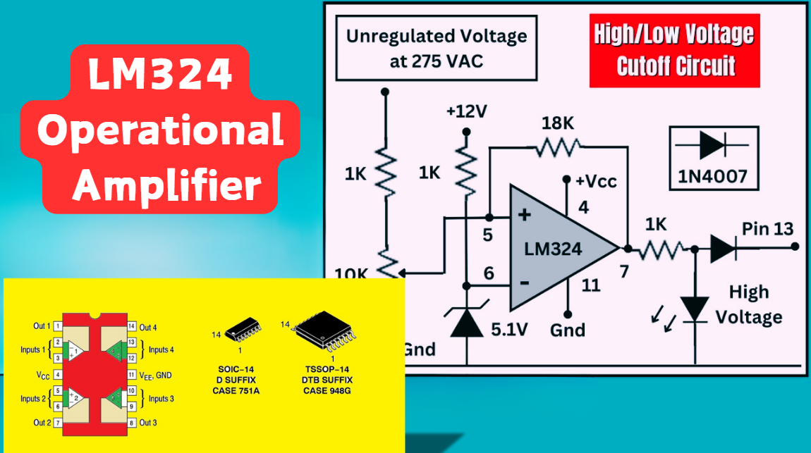
LM324 Operational Amplifier Comprehensive Guide: Pins, Applications, Packaging, and Datasheet
The LM324 is a low-cost integrated circuit featuring four independent operational amplifiers (op-amps), renowned for its wide voltage adaptability, low power consumption, and high reliability in industrial and consumer electronics. With a single-supply voltage range of 3V to 32V (or dual-supply rang...
-
2025 / 07 / 02
A Comprehensive Guide to Replacing Opto-Couplers with Digital Isolators: From Principles to Practice
In the ever-evolving landscape of electronic design, the transition from opto-couplers to digital isolators marks a pivotal shift in isolation technology. For decades, opto-couplers have been the cornerstone of electrical isolation in industrial control, medical devices, and power systems, relying o...
-
2025 / 06 / 30
Multivariate Application Analysis of Power Amplifiers in Sensor Testing
In the field of modern sensor testing, power amplifiers (PAs) serve as core components and play an indispensable role. From amplifying weak signals to simulating complex physical environments, power amplifiers provide solid guarantees for the precise testing of sensor performance through their uniqu...
-
2025 / 06 / 28
ESP32 vs STM32: Which Microcontroller Suits You Better?
In the field of embedded development, both ESP32 and STM32 are highly favored microcontrollers, each with unique features and advantages. When facing project development, how do you choose between them? This requires comprehensive consideration of multiple factors. The following detailed comparison ...
-
2025 / 06 / 26
Key Strategies to Enhance Buck Power Supply Efficiency
Improving the efficiency of Buck (step-down) switching power supplies requires a multi-dimensional approach targeting energy loss sources, including component selection, topology optimization, control strategies, and thermal management. Below are core strategies and engineering practices:...
-
2025 / 06 / 26
P-Channel MOSFET Turn-On Conditions
The turn-on conditions for a P-channel MOSFET (PMOS) are inverse to those of an N-channel MOSFET (NMOS), primarily governed by the relationship between the gate-source voltage (VGS) and the threshold voltage (Vth), along with voltage polarity. Here are the key points:A PMOS turns on when its gate vo...
-
2025 / 06 / 24
A8304SESTR-T Allegro MicroSystems-Single LNB Supply and Control Voltage Regulator
The Allegro MicroSystems A8304SESTR-T is a single-channel Low Noise Block Regulator (LNBR). It integrates a monolithic boost converter with MOSFET, current sensing, and compensation. Featuring a 704 kHz switching frequency, it uses few external components. With an I²C-compatible interface, it offers...
-
2025 / 06 / 20
EG25GGC-128-SGNS by Quectel Wireless Solutions Co., Ltd: Features,Symbol,Footprint and Datasheet
The Quectel EG25GGC - 128 - SGNS is an LTE Cat 4 module optimized for M2M and IoT. Supporting 3GPP Rel. 11, it offers up to 150Mbps downlink and 50Mbps uplink. With global LTE/UMTS/GSM coverage, it's backward - compatible with EDGE/GPRS. Featuring multi - constellation GNSS (GPS, GLONASS, BeiDou, et...

2000+
Daily average RFQ Volume

30,000,000
Standard Product Unit

2800+
Worldwide Manufacturers

15,000 m2
In-stock Warehouse
 Wishlist (0 Items)