

- RFQ
- BOM
-
Contact Us
Tel: +86-0755-83501315
Email: sales@sic-components.com


- Chinese
- English
- French
- German
- Portuguese
- Spanish
- Russian
- Japanese
- Korean
- Arabic
- Irish
- Greek
- Turkish
- Italian
- Danish
- Romanian
- Indonesian
- Czech
- Afrikaans
- Swedish
- Polish
- Basque
- Catalan
- Esperanto
- Hindi
- Lao
- Albanian
- Amharic
- Armenian
- Azerbaijani
- Belarusian
- Bengali
- Bosnian
- Bulgarian
- Cebuano
- Chichewa
- Corsican
- Croatian
- Dutch
- Estonian
- Filipino
- Finnish
- Frisian
- Galician
- Georgian
- Gujarati
- Haitian
- Hausa
- Hawaiian
- Hebrew
- Hmong
- Hungarian
- Icelandic
- Igbo
- Javanese
- Kannada
- Kazakh
- Khmer
- Kurdish
- Kyrgyz
- Latin
- Latvian
- Lithuanian
- Luxembou..
- Macedonian
- Malagasy
- Malay
- Malayalam
- Maltese
- Maori
- Marathi
- Mongolian
- Burmese
- Nepali
- Norwegian
- Pashto
- Persian
- Punjabi
- Serbian
- Sesotho
- Sinhala
- Slovak
- Slovenian
- Somali
- Samoan
- Scots Gaelic
- Shona
- Sindhi
- Sundanese
- Swahili
- Tajik
- Tamil
- Telugu
- Thai
- Ukrainian
- Urdu
- Uzbek
- Vietnamese
- Welsh
- Xhosa
- Yiddish
- Yoruba
- Zulu
- Kinyarwanda
- Tatar
- Oriya
- Turkmen
- Uyghur
Active Filter Ic
An active filter is an electronic circuit that combines active components (such as operational amplifiers or transistors) with passive components (resistors and capacitors) to selectively process specific frequency components of a signal. Unlike passive filters— which rely solely on resistors, capacitors, and inductors—active filters can amplify weak signals, offer precise control over frequency response, and feature high input impedance/low output impedance for efficient signal handling. Their core functions include:
Frequency Selectivity: Allowing, reducing, or blocking specific frequency bands.
Signal Amplification: Boosting low-level signals (e.g., from sensors or microphones) during filtering.
Noise Mitigation: Enhancing signal quality by rejecting unwanted interference.
Theoretical Basis of Active Filters
The design of active filters is grounded in linear system theory and feedback principles, enabling precise manipulation of signal characteristics:
Transfer Function: A mathematical model describing the relationship between input and output signals in the frequency domain. It helps analyze how the filter modifies amplitude and phase across different frequencies.
Op-Amp Feedback Networks: Operational amplifiers (op-amps) in negative feedback configurations (such as non-inverting or inverting setups) shape the filter’s frequency response. Feedback allows engineers to adjust key parameters like the cutoff frequency (the boundary between passed and attenuated frequencies), quality factor (which determines bandwidth narrowness), and roll-off rate (how sharply frequencies outside the passband are attenuated).
Bode Plots: Graphical tools used to visualize how the filter’s gain (in decibels) and phase shift change with frequency, aiding in the analysis of amplitude and phase responses.
Filter Approximation Techniques: Methods like Butterworth (ensuring a smooth, flat response in the passband), Chebyshev (achieving steeper roll-offs with controlled ripple), and Elliptic (offering the sharpest transitions between passband and stopband, with ripple in both bands) guide the design of higher-order filters for specific applications.
The Active Power Filter Working Principle
Active Power Filters (APFs) are specialized devices designed to improve power quality in electrical systems by dynamically compensating for harmonics, reactive power, and unbalanced loads. Their operation involves three key stages:
Harmonic Detection:
Current sensors measure the load current, which includes both the fundamental frequency (e.g., 50/60 Hz) and unwanted harmonic components (multiples of the fundamental frequency, such as 3rd, 5th, and 7th harmonics).
Digital signal processors (DSPs) or field-programmable gate arrays (FPGAs) use algorithms to isolate these harmonic components from the desired fundamental current.
Compensation Signal Generation:
The control system creates a reference signal that matches the amplitude of the harmonic current but has the opposite phase, ensuring it will cancel out the harmonics.
Power Conversion and Injection:
A PWM inverter (using power semiconductors like IGBTs) converts this reference signal into a compensating current, which is injected into the power grid. This cancels the harmonic current, resulting in a near-sinusoidal source current that improves power factor and reduces distortion.
Types of Active Filters
Active filters are categorized by the frequency bands they allow or reject:
Low-Pass Filter (LPF):
Function: Passes low frequencies below a cutoff point while attenuating higher frequencies.
Circuit: Uses an op-amp with a resistor-capacitor (RC) network at the input. For higher-order designs (steeper roll-offs), topologies like Sallen-Key are employed.
Example: Removing high-frequency noise from audio signals to improve clarity.
High-Pass Filter (HPF):
Function: Passes high frequencies above a cutoff point while attenuating lower frequencies (e.g., DC offsets or low-frequency hum).
Circuit: Incorporates an op-amp with an RC network configured to block low frequencies.
Example: Eliminating slow DC drift from biomedical signals like ECGs to enhance signal accuracy.
Band-Pass Filter (BPF):
Function: Allows a specific band of frequencies (between a lower and upper cutoff) to pass through while rejecting frequencies outside this range.
Circuit: Often formed by cascading a high-pass filter (for the lower cutoff) and a low-pass filter (for the upper cutoff), or using topologies like Multiple Feedback (MFB) for higher selectivity.
Example: Tuning into specific radio frequency bands in communication systems to isolate desired signals.
Band-Stop Filter (Notch Filter):
Function: Attenuates a specific frequency band while allowing all other frequencies to pass through.
Circuit: Created by parallelizing high-pass and low-pass filters and using a summing amplifier, or via specialized networks like twin-T filters for narrow notches.
Example: Removing 50/60 Hz hum from audio recordings or biomedical signals caused by mains interference.
All-Pass Filter:
Function: Passes all frequencies without attenuation but modifies their phase relationship, useful for equalizing phase responses in audio systems.
Components Used in Active Filters
Operational Amplifiers (Op-Amps):
Role: Provide signal amplification, buffering (to prevent loading of the signal source), and enable feedback for shaping frequency response.
Key Parameters:
Gain-Bandwidth Product (GBP): Must be sufficiently high to handle the highest signal frequency for stable operation.
Input Impedance: High impedance (e.g., greater than 1 MΩ) ensures minimal loading of the source.
Noise Specifications: Critical for low-level signals, with low-noise op-amps preferred in applications like audio processing.
Passive Components (Resistors and Capacitors):
Resistors (R): Set the filter’s gain (via feedback networks) and define time constants in conjunction with capacitors, which influence the cutoff frequency.
Capacitors (C): Determine the cutoff frequency based on their values and the resistors they pair with. Ceramic or film capacitors are used for high-frequency applications, while electrolytic capacitors are suitable for power supply filtering.
Transistors:
Role: Act as amplifying elements in simpler circuits or low-power applications, such as basic BJT-based filters.
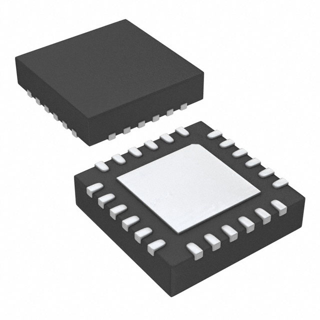
Integrated Circuits (ICs):
Active Filter ICs: Pre-integrated solutions that combine op-amps, resistors, and capacitors on a single chip (e.g., MAX274 for switched-capacitor filters, UAF42 for state-variable filters). These ICs offer configurable parameters via external components, simplifying design.
Why are Active Filters Important?
Signal Amplification: Unlike passive filters, which can only attenuate signals, active filters can amplify weak inputs, making them essential for sensor-based applications.
Precision and Flexibility: Enable sharp roll-offs, adjustable selectivity (via the quality factor), and complex frequency responses, catering to demanding applications like biomedical signal processing.
Impedance Matching: High input impedance preserves the integrity of the signal source, while low output impedance ensures efficient driving of loads like speakers or analog-to-digital converters (ADCs).
Compact Design: Avoid the use of bulky inductors (common in passive filters), making them ideal for portable devices and high-density circuit boards.
Stability: Feedback networks in active filters reduce the risk of resonance caused by impedance mismatches, a common issue in passive LC filters.
Applications of Active Filter ICs
Audio and Acoustics:
Equalization: Adjusting frequency response in audio devices to enhance bass or treble.
Crossover Networks: Separating low frequencies for woofers and high frequencies for tweeters in speaker systems using cascaded low-pass and high-pass filters.
Communications Systems:
Channel Selection: Using band-pass ICs in radios to isolate specific frequency bands for FM/AM tuning.
Signal Conditioning: Removing interference from data links (e.g., DSL filters) to improve communication reliability.
Biomedical Engineering:
ECG/EEG Processing: Notch filters to eliminate mains interference and high-pass filters to remove DC drift from biological signals.
Pacemakers: Low-noise active filters to amplify and clean up weak bioelectric signals for accurate monitoring.
Power Electronics:
Active Power Filters (APFs): Mitigating harmonics generated by industrial loads like variable-frequency drives (VFDs) to improve grid quality.
DC-DC Converters: Filtering output ripple with low-pass ICs to ensure stable voltage supply in power systems.
Data Acquisition:
Anti-Aliasing: Low-pass filters before ADCs to limit bandwidth and comply with Nyquist sampling requirements.
Signal Reconstruction: Smoothing outputs from digital-to-analog converters (DACs) in audio systems using band-pass filters.
Advantages of Active Filter ICs in These Applications
Integration: Reduce component count and design complexity by integrating multiple functions (e.g., op-amps, resistors) into a single chip, saving board space.
Adjustability: External resistors or capacitors allow quick tuning of parameters like cutoff frequency and quality factor without redesigning the entire circuit.
Low Noise Performance: Optimized internal layouts in ICs minimize noise pickup, critical for sensitive applications like biomedical devices.
Reliability: Tight component tolerances ensure consistent performance across varying temperatures and voltages, enhancing stability.
Advantages of Active Filter ICs
Gain Provision: Amplify signals during filtering, essential for low-level inputs from sensors or microphones.
High Selectivity: Achieve high quality factors (Q), enabling narrowband filtering for applications like radio frequency tuning, which passive filters struggle to match due to energy losses in inductors.
Adaptability: Easily reconfigurable for different frequency ranges by changing external components, making them suitable for multi-standard devices (e.g., Bluetooth and Wi-Fi radios).
Energy Efficiency: No power dissipation in inductors (a common issue in passive filters), improving battery life in portable electronics.
Design Simplicity: Pre-defined topologies in IC datasheets streamline the design process, making them accessible to engineers with varying levels of experience.
Active Filter Design Considerations
Frequency Response:
Define Requirements: Specify passband gain (how much the filter amplifies desired frequencies), stopband attenuation (how much it reduces unwanted frequencies), and transition width (the range between passband and stopband).
Topology Selection:
Low Selectivity (broad bandwidth): Use simple Sallen-Key topologies for low component count.
High Selectivity (narrow bandwidth): Opt for Multiple Feedback (MFB) or state-variable topologies to achieve higher Q factors.
Multi-Output Needs: State-variable filters that generate simultaneous low-pass, high-pass, and band-pass outputs.
Filter Order:
First-Order: Suitable for basic noise reduction with gentle roll-offs (e.g., an RC filter paired with an op-amp buffer).
Higher-Order: Required for steeper roll-offs (e.g., 40 dB/decade for second-order filters) but come with increased complexity and potential stability risks.
Practical Rule: Choose the lowest order that meets attenuation requirements to balance performance and simplicity.
Component Selection:
Op-Amp Choice: Prioritize op-amps with sufficient bandwidth (gain-bandwidth product at least 10x the highest signal frequency) and low noise for precision applications.
Passive Components: Use tight-tolerance resistors and capacitors (1% for precision filters, 5% for non-critical uses) and select capacitor types (e.g., NP0 ceramic for stability) based on frequency and environmental requirements.
Stability and Compensation:
Phase Margin Analysis: Ensure the filter has a phase margin of at least 45° to prevent oscillations, using tools like Bode plots for analysis.
Compensation Techniques: Add small capacitors in feedback paths for high-gain circuits and use decoupling capacitors near op-amp power pins to filter noise.
Layout Practices: Keep traces short, use ground planes for low-impedance paths, and separate analog and digital grounds to minimize noise coupling.
Mitigation of Noise and Distortion:
Power Supply Filtering: Use LC filters on power rails to reduce ripple and noise from the power source.
Input Protection: Include small series resistors at op-amp inputs to limit current surges and reduce distortion from overloads.
Shielding: Encase high-frequency filters in grounded metal shields to block electromagnetic interference (EMI) in sensitive applications.
Difference between Active and Passive Filters
Feature Active Filters Passive Filters
Components Op-amps, transistors + resistors, capacitors Resistors, inductors, capacitors (no active parts)
Power Requirement Needs external DC power (e.g., for op-amps) Operates on input signal energy (no external power)
Gain Provides voltage gain (e.g., amplifies weak signals) No gain; may attenuate signals due to component losses
Frequency Range Best for low-to-mid frequencies (<10 MHz) Effective across all frequencies (including RF/DC)
Selectivity (Q Factor) High (enables narrow bandwidths) Low (limited by energy losses in inductors/resistors)
Impedance High input impedance, low output impedance Impedance varies with frequency (may cause loading)
Size Compact (no bulky inductors in most designs) Larger (inductors are sizeable, especially at low frequencies)
Complexity Moderate to high (involves feedback and power supply) Simple (passive component combinations)
Typical Applications Audio processing, biomedical signals, data acquisition Power supply filtering, RF matching, high-power systems
To Sum Up
Active filters are essential in modern electronics, leveraging active components to deliver precise, amplifying, and adaptable frequency processing. Their theoretical foundation in feedback control and system analysis allows for diverse designs, from simple low-pass filters to advanced active power filters for grid harmonics. Key advantages—such as gain capability, high selectivity, and compactness—make them ideal for applications requiring signal conditioning, noise reduction, and dynamic response. While design considerations like stability and component selection require careful attention, their versatility and performance make them indispensable in fields ranging from audio engineering to renewable energy. As technology trends toward miniaturization and 智能化,active filters—especially integrated ICs—will continue to drive innovation in signal processing, enabling more efficient and sophisticated electronic systems.
https://www.sic-components.com/filters
Hot Products
View More-
5903_N-50-6/133_NE Huber+Suhner, Inc.
-
6603_SK-50-1/199_NE Huber+Suhner, Inc.
-

22659280 Huber+Suhner, Inc.
-
6607_SMA-50-3/199_NE Huber+Suhner, Inc.
-
ATT-0290-04-SMA-02 Cinch Connectivity Solutions Midwest Microwave
-
BW-30N100W+ Mini-Circuits
-
E-TA2012 T 6DB N8 Nidec Components Corporation
-
AMMP-6650-BLKG Broadcom Limited
-
6805.17.A Huber+Suhner, Inc.
-
PXV1220S-3DBN8-T Susumu
-
E-TA3216 T 5DB N8 Nidec Components Corporation
-
C-ATTNS-ASCPC-9DB ProLabs
Related Blogs
-
2025 / 08 / 01
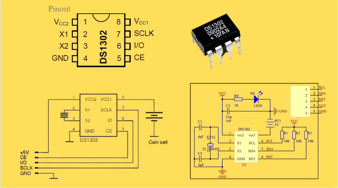
DS1302 RTC: Datasheet,Attributes,Features,Applications
As a low-power device widely used in electronic equipment, the DS1302 is centered on accurate real-time clock/calendar recording functions. It supports full-dimensional tracking of seconds, minutes, hours, days, weeks, months, and years, features automatic leap year compensation, and is compatible w...
-
2025 / 07 / 30
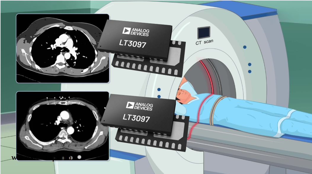
LT3097 Dual 500 mA, positive/negative, ultralow noise, ultrahigh PSRR low dropout linear regulator
The LT3097 is a dual, positive and negative, high-performance, low-dropout linear regulator featuring Analog Devices, Inc., ultralow noise and ultra-high power supply rejection ratio (PSRR) architecture for powering noise-sensitive applications. Each regulator delivers up to 500 mA with a typical 26...
-
2025 / 07 / 28
What is a Digital Integrated Circuit?
In the fast - paced world of modern electronics, digital integrated circuits (ICs) are the unsung heroes that power everything from our smartphones and laptops to complex supercomputers and industrial control systems. But what exactly is a digital integrated circuit?...
-
2025 / 07 / 25
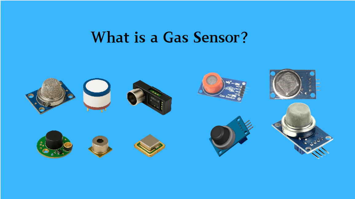
What is a Gas Sensor?
A gas sensor is a device that can convert information such as the composition and concentration of gas into electrical signals recognizable by electronic equipment. It is like the "olfactory organ" of an electronic system, capable of acutely detecting the presence of specific gases in the environmen...
-
2025 / 07 / 24
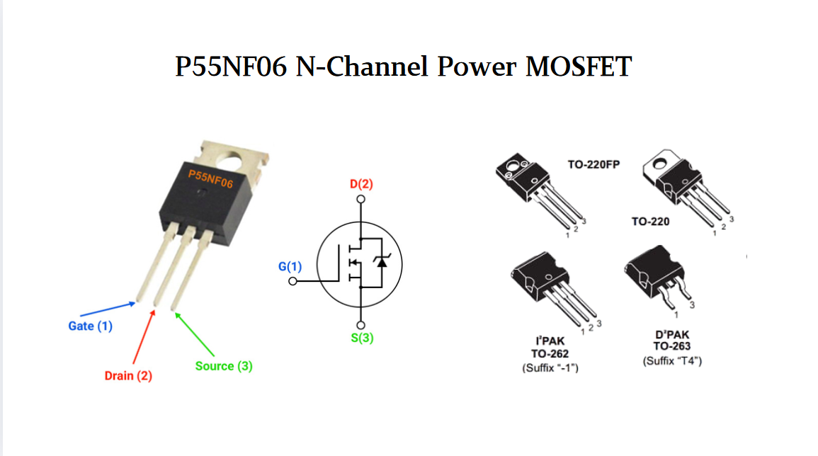
P55NF06 N-Channel Power MOSFET: Everything You Need To Know
In the vast landscape of semiconductor devices, MOSFETs (Metal - Oxide - Semiconductor Field - Effect Transistors) play a pivotal role, especially in power electronics. Among the numerous MOSFET models available, the P55NF06 stands out for its unique combination of features, making it suitable for a...
-
2025 / 07 / 23
Operational Amplifier Filters: A Comprehensive Analysis from Fundamentals to Applications
In electronic systems, the purity and accuracy of signals directly determine the performance of devices. Electronic filters composed of operational amplifiers (op-amps) have become a "bridge" connecting original signals and valid information, thanks to their ability to precisely filter signal freque...
-
2025 / 07 / 19
Broadcom BCM5714CKPB: Featrues,Applications,Datasheet And Advantages
When it comes to reliable, high-performance network connectivity in enterprise and industrial systems, the Broadcom BCM5714CKPB stands as a standout solution. This dual-port Gigabit Ethernet controller, developed by Broadcom—a leader in semiconductor innovation—combines robust features, versatile co...
-
2025 / 07 / 15
MC7447AHX1000NB: Technical Analysis and Applications of a High-Performance PowerPC Architecture Proc
In the field of embedded computing and network systems, the performance, energy efficiency, and compatibility of processors are often crucial to the success of a design. The MC7447AHX1000NB launched by NXP (formerly Freescale), as an important member of the MPC7447A series, has become an ideal choic...
-
2025 / 07 / 14
Nexperia Unveils New 1200V/20A SiC Schottky Diodes to Empower Efficient Industrial Power Innovations
Nexperia recently announced the addition of two new 1200V, 20A silicon carbide (SiC) Schottky diodes—PSC20120J and PSC20120L—to its power electronics portfolio, further expanding its product landscape in high-performance semiconductors. Specifically designed to address the increasingly stringent dem...

-
2025 / 07 / 09
CD4007: A Comprehensive Analysis of a Multifunctional CMOS Integrated Circuit
In the field of modern electronic technology, CMOS (Complementary Metal-Oxide-Semiconductor) integrated circuits have become core components in digital and analog circuit design due to their low power consumption, high integration, and excellent compatibility. As a classic CMOS device, the CD4007 oc...


2000+
Daily average RFQ Volume

30,000,000
Standard Product Unit

2800+
Worldwide Manufacturers

15,000 m2
In-stock Warehouse
 Wishlist (0 Items)