

- RFQ
- BOM
-
Contact Us
Tel: +86-0755-83501315
Email: sales@sic-components.com


- Chinese
- English
- French
- German
- Portuguese
- Spanish
- Russian
- Japanese
- Korean
- Arabic
- Irish
- Greek
- Turkish
- Italian
- Danish
- Romanian
- Indonesian
- Czech
- Afrikaans
- Swedish
- Polish
- Basque
- Catalan
- Esperanto
- Hindi
- Lao
- Albanian
- Amharic
- Armenian
- Azerbaijani
- Belarusian
- Bengali
- Bosnian
- Bulgarian
- Cebuano
- Chichewa
- Corsican
- Croatian
- Dutch
- Estonian
- Filipino
- Finnish
- Frisian
- Galician
- Georgian
- Gujarati
- Haitian
- Hausa
- Hawaiian
- Hebrew
- Hmong
- Hungarian
- Icelandic
- Igbo
- Javanese
- Kannada
- Kazakh
- Khmer
- Kurdish
- Kyrgyz
- Latin
- Latvian
- Lithuanian
- Luxembou..
- Macedonian
- Malagasy
- Malay
- Malayalam
- Maltese
- Maori
- Marathi
- Mongolian
- Burmese
- Nepali
- Norwegian
- Pashto
- Persian
- Punjabi
- Serbian
- Sesotho
- Sinhala
- Slovak
- Slovenian
- Somali
- Samoan
- Scots Gaelic
- Shona
- Sindhi
- Sundanese
- Swahili
- Tajik
- Tamil
- Telugu
- Thai
- Ukrainian
- Urdu
- Uzbek
- Vietnamese
- Welsh
- Xhosa
- Yiddish
- Yoruba
- Zulu
- Kinyarwanda
- Tatar
- Oriya
- Turkmen
- Uyghur
Current Limiter
1. Introduction
A current limiter is a crucial device or circuit element meticulously engineered to govern and restrict the flow of electric current within an electrical system. At its core, it acts as a safeguard, monitoring the current levels and intervening when necessary to maintain them within safe and optimal boundaries. In an electrical circuit, current naturally flows from a source of higher electrical potential to a lower one, powering various components along the way. However, under certain circumstances, such as a short - circuit or an overload, the current can surge to dangerous levels. This is where the current limiter steps in. Its basic role is to detect these abnormal current increases and take appropriate action to either reduce the current or interrupt the circuit entirely, thereby maintaining the safety and proper operation of electrical circuits. By doing so, it prevents components from being subjected to excessive electrical stress, which could lead to damage, malfunction, or even pose a fire hazard.
2. Types of Current Limiters
2.1 Passive Current Limiters
Resistors
Resistors are one of the simplest yet effective passive current limiters. When placed in series with a load, they impede the flow of current. According to Ohm's Law (\(I = \frac{V}{R}\), where I is the current, V is the voltage across the resistor, and R is the resistance), the resistance value of the resistor determines the amount of current that can flow through the circuit. For example, if a 10 - volt power source is connected to a 5 - ohm resistor in series with a load, the current flowing through the circuit would be \(I=\frac{10V}{5\Omega}= 2\) amperes. To calculate the appropriate resistor value for a given application, engineers need to know the voltage of the power source and the maximum allowable current for the load. However, resistive current limiters have limitations. As current passes through them, they dissipate power in the form of heat. This heat generation can be a concern, especially in circuits where high currents or long - term operation are involved, as it may require additional cooling mechanisms and can reduce the overall efficiency of the circuit.
Fuses
Fuses are current - sensitive devices designed to protect circuits from overcurrent. Structurally, they typically consist of a thin wire or strip of metal enclosed in a housing. When the current flowing through the fuse exceeds its rated value, the heat generated by the current causes the metal element to melt, breaking the circuit and interrupting the current flow. There are different types of fuses, each with its own characteristics and applications. Fast - acting fuses are designed to blow quickly when an overcurrent occurs, making them suitable for protecting sensitive electronic components that can be damaged rapidly by high currents. Slow - blow fuses, on the other hand, can tolerate short - term current surges, such as those that occur during the startup of motors, and are used in applications where such transient overcurrents are normal. The advantages of fuses include their simplicity and low cost. They are easy to install and replace. However, once a fuse has blown, it needs to be physically replaced, which can be inconvenient, especially in hard - to - reach locations or in systems that require continuous operation.
Thermistors
Thermistors are temperature - sensitive resistors that can be used for current limiting. Negative temperature coefficient (NTC) thermistors have a resistance that decreases as the temperature increases, while positive temperature coefficient (PTC) thermistors have a resistance that increases with temperature. NTC thermistors are commonly used to limit inrush current, which is the large surge of current that occurs when a device is first connected to a power source. When cold, an NTC thermistor has a relatively high resistance, which restricts the initial current flow. As the current passes through it, the thermistor heats up, and its resistance decreases, allowing the normal operating current to flow. PTC thermistors, on the other hand, act as resettable fuses. When the current through a PTC thermistor exceeds a certain level, the heat generated causes its resistance to increase dramatically, effectively limiting the current. Once the overcurrent condition is removed and the thermistor cools down, its resistance returns to a lower value, and the circuit can resume normal operation. While thermistors offer useful current - limiting capabilities, they also have limitations. Their performance can be affected by ambient temperature, and they may not be suitable for applications that require extremely precise current control.
2.2 Active Current Limiters
Transistors
Transistors, including bipolar junction transistors (BJTs) and field - effect transistors (FETs), can be used in current - limiting circuits. In a current - limiting application, transistors function by sensing and controlling the current through the load by adjusting the voltage across it. For example, in a common - emitter configuration using a BJT, the base - emitter voltage controls the collector - emitter current. By carefully designing the biasing circuit and using appropriate feedback mechanisms, the transistor can be made to limit the current flowing through the load. FETs, on the other hand, can control the current by varying the voltage applied to their gate terminal. Transistor - based current limiters offer several advantages over passive devices. They can provide more precise current control, allowing for fine - tuning of the current levels. Additionally, they have faster response times, enabling them to react quickly to sudden changes in current, which is crucial in protecting sensitive components from short - lived overcurrent spikes.
Diodes
Current - limiting diodes (CLDs), also known as constant - current diodes, are designed to maintain a relatively constant current over a wide range of voltages. These diodes are typically based on a JFET (Junction Field - Effect Transistor) with its gate and source shorted. This unique structure gives them the ability to regulate the current flowing through them, similar to how a zener diode maintains a constant voltage. When the voltage across the CLD increases, the internal resistance of the diode adjusts to keep the current approximately constant. CLDs are useful in circuits where a stable current supply is required, such as in LED driving circuits, where maintaining a consistent current ensures the LED operates at a stable brightness and has a longer lifespan.
Integrated Circuit (IC) Current Limiters
Current - limiting ICs are highly sophisticated devices that incorporate advanced current - sensing and control mechanisms. These ICs often come with built - in analog - to - digital converters (ADCs) to accurately sense the current flowing through the load. They can be programmed or configured, either through external pins or via software interfaces, to set specific current limits. Using feedback control loops, they continuously monitor the current and adjust the output voltage or current to regulate the load current precisely. Some current - limiting ICs also use pulse - width modulation (PWM) techniques to achieve efficient current regulation. The benefits of using IC current limiters are numerous. They offer high precision in current control, allowing for accurate protection of components. Their flexibility in programming and configuration makes them adaptable to a wide variety of circuit designs. Moreover, by integrating multiple functions into a single chip, they can simplify circuit designs and reduce the overall component count, leading to smaller, more reliable electrical systems.
3. Working Principles of Current Limiters
3.1 Current Sensing Mechanisms
Current limiters employ various methods to sense the current flowing through a circuit. One common approach is to measure the voltage drop across a sense resistor placed in series with the load. According to Ohm's Law, the voltage drop across the resistor is directly proportional to the current flowing through it. By measuring this voltage with a high - precision amplifier and analog - to - digital converter, the current value can be accurately determined. Another method involves using Hall - effect sensors. These sensors detect the magnetic field generated by the current - carrying conductor. The strength of the magnetic field is proportional to the current, and the Hall - effect sensor converts this magnetic field into an electrical signal that can be measured and processed to determine the current. Other current - sensing techniques include using current transformers, which work on the principle of electromagnetic induction to isolate and measure the current, and Rogowski coils, which are flexible, non - invasive current sensors that can be used to measure high - frequency or large - amplitude currents. Once the current is sensed, the information is processed and compared with a pre - defined current limit threshold. This comparison is typically done using comparator circuits or digital signal processing algorithms in the case of more advanced current limiters.
3.2 Current Limiting Processes
For passive current limiters
Resistors limit current by dissipating power as heat and creating a voltage drop according to Ohm's Law. As the current passes through the resistor, the electrical energy is converted into heat energy, reducing the amount of current available for the load. Fuses operate by melting and interrupting the circuit when the current exceeds their rated value. The heat generated by the excessive current causes the fuse element to reach its melting point, breaking the electrical connection and stopping the current flow. Thermistors change their resistance with temperature to limit current. NTC thermistors reduce inrush current by presenting a high resistance initially and then decreasing their resistance as they heat up. PTC thermistors increase their resistance when the current exceeds a certain level, effectively reducing the current and protecting the circuit. Once the overcurrent condition is removed, PTC thermistors can cool down and return to their normal resistance state.
For active current limiters
Transistors adjust the conductivity to control the current flow by regulating the voltage across the load. By changing the base - emitter voltage in a BJT or the gate - source voltage in a FET, the amount of current that can pass through the transistor and reach the load can be controlled. Current - limiting diodes maintain a constant current by utilizing the internal characteristics of their semiconductor structure. The shorted gate - to - source connection in a JFET - based CLD allows it to adjust its internal resistance in response to changes in voltage, ensuring a relatively stable current output. Current - limiting ICs use feedback control loops, pulse - width modulation (PWM), or other advanced techniques to limit and regulate the current precisely. The feedback control loop continuously monitors the current and adjusts the output of the IC to keep the current at the desired level. PWM can be used to vary the average current by rapidly switching the output on and off at a high frequency, allowing for efficient current regulation while minimizing power loss.
4. Applications of Current Limiters
4.1 Power Supplies
In power supply circuits, current limiters play a vital role in protecting the power source and connected loads. Power supplies are designed to deliver a specific amount of current to the load. However, in the event of a short circuit in the load or an accidental connection of a device with a much lower resistance than expected, the current can increase rapidly, potentially damaging the power supply's internal components. Current limiters in power supplies detect these overcurrent conditions and either reduce the output current to a safe level or shut down the power supply entirely. For switching power supplies, which are widely used due to their high efficiency, current - limiting ICs are often employed. These ICs can quickly respond to changes in load current and use advanced control techniques like PWM to regulate the current precisely. In linear power supplies, resistive or transistor - based current limiters may be used to protect the voltage - regulating components and the load from overcurrent.
4.2 Electronic Devices
Consumer Electronics
In consumer electronics products such as smartphones, laptops, tablets, and digital cameras, current limiters are essential for protecting internal components from overcurrent. These devices contain a variety of sensitive integrated circuits, batteries, and other components that can be easily damaged by excessive current. For example, during the battery charging process, current limiters in the charging circuits ensure that the battery is charged at a safe and controlled rate. They prevent overcharging, which can lead to battery swelling, reduced lifespan, or even pose a fire hazard. Additionally, current limiters protect the delicate circuitry inside these devices from transient overcurrents that can occur when connecting external peripherals or during power - on sequences.
Industrial Electronics
In industrial settings, current limiters are crucial for safeguarding equipment in industrial control systems, programmable logic controllers (PLCs), and motor drives. Motors, which are widely used in industrial applications, can draw large currents during startup or when they encounter a mechanical stall. Current limiters in motor drives detect these abnormal current levels and either reduce the power supplied to the motor or apply braking mechanisms to prevent damage to the motor windings and the drive electronics. PLCs, which control various industrial processes, also rely on current limiters to protect their internal components from overcurrent caused by faulty sensors, actuators, or other connected devices. By ensuring the reliable operation of these components, current limiters contribute to the smooth and continuous operation of industrial production lines.
4.3 Lighting Systems
LED Lighting
LEDs require a stable and regulated current to operate efficiently and have a long lifespan. Current limiters in LED drivers are essential for providing this consistent current. Different types of current limiters, such as current - limiting diodes and current - limiting ICs, are used depending on the specific requirements of the LED lighting application. For example, in a high - power LED lighting fixture, a current - limiting IC may be used to precisely control the current flowing through multiple LEDs connected in series or parallel. This ensures that each LED receives the same amount of current, resulting in uniform brightness and preventing any single LED from being damaged due to overcurrent. Additionally, current limiters help optimize the energy efficiency of LED lighting systems by reducing power losses and ensuring that the LEDs operate at their optimal current levels.
Fluorescent Lighting
In fluorescent lighting ballasts, current limiters are used to control the current flow through the fluorescent tubes. The ballast provides the necessary electrical conditions for the fluorescent tube to start and operate. Current limiters in the ballast ensure that the current through the tube remains within the safe operating range. They prevent excessive current, which could cause the tube to overheat, flicker, or fail prematurely. By regulating the current, current limiters also help improve the efficiency and lifespan of the fluorescent lighting system.
4.4 Battery - Related Applications
Battery Chargers
Battery chargers use current limiters to protect the battery from overcharging. Overcharging can cause chemical reactions within the battery that degrade its performance and lifespan. Current limiters in battery chargers monitor the charging current and adjust it as needed to ensure that the battery is charged at an optimal rate. They may use techniques such as constant - current charging followed by constant - voltage charging to safely charge the battery. Once the battery reaches a certain voltage level, the current limiter reduces the charging current to prevent overcharging. This not only protects the battery but also ensures a safe and efficient charging process.
Battery - Powered Devices
In battery - powered devices, current limiters are used to limit the current drawn from the battery during operation. This helps prevent excessive discharge, which can damage the battery and reduce its overall capacity. For example, in a portable power tool, the current limiter ensures that the motor does not draw more current than the battery can safely supply. By limiting the current, the device can operate for a longer period without damaging the battery, and the battery's lifespan is extended. Additionally, current limiters can protect the device's internal electronics from overcurrent caused by short circuits or faulty components within the device.
5. Advantages and Disadvantages of Current Limiters
5.1 Advantages
Component Protection
Current limiters are highly effective in safeguarding electrical components from damage caused by overcurrent. Components such as resistors, capacitors, integrated circuits, and motors are all vulnerable to the harmful effects of excessive current. For instance, overcurrent can cause resistors to overheat and change their resistance value, damage the delicate internal circuitry of integrated circuits, or burn out the windings of motors. By limiting the current, current limiters prevent these components from being subjected to excessive electrical stress, thereby extending their lifespan and ensuring the long - term reliability of the overall electrical system.
System Reliability
By preventing overcurrent - related failures, current limiters significantly enhance the reliability of electrical systems. Overcurrent can lead to unexpected breakdowns, which can cause disruptions in operations, especially in critical applications such as data centers, hospitals, and industrial production lines. Current limiters act as a safeguard, reducing the likelihood of such failures and ensuring that the system operates smoothly. This not only minimizes downtime but also reduces the costs associated with repairs and maintenance, making the electrical system more cost - effective in the long run.
Safety Enhancement
Current limiters play a crucial role in enhancing the safety of electrical systems. Excessive current can generate heat, which, if not controlled, can lead to fires or electrical shocks. By limiting the current, current limiters prevent the overheating of components and the associated fire hazards. They also reduce the risk of electrical shocks by ensuring that the current levels remain within safe limits, protecting both the equipment and the personnel who interact with the electrical system.
Flexibility and Adaptability
The wide variety of current limiters available, including passive and active types, offers different levels of flexibility and adaptability. Different circuits have unique requirements in terms of current levels, response times, and operating conditions. For example, a simple resistive current limiter may be sufficient for a low - power, basic circuit, while a more complex current - limiting IC may be required for a high - precision, high - speed circuit. This flexibility allows engineers to select the most appropriate current limiter for a given application, ensuring optimal performance and protection.
5.2 Disadvantages
Cost
Some advanced current limiters, particularly active devices and integrated circuits, can be significantly more expensive
than simpler passive current - limiting solutions. The higher cost of active current limiters stems from their complex internal structures, advanced manufacturing processes, and the integration of multiple functions. For instance, a current - limiting IC with sophisticated current - sensing and control features may cost several times more than a basic fuse or a simple resistive current limiter. This increased cost can add up, especially in large - scale electrical systems or mass - produced consumer electronics, where numerous current limiters are required. As a result, it may increase the overall production cost of electrical products, potentially making them less competitive in the market.
Complexity
Designing and implementing current - limiting circuits involving active components and integrated circuits can be highly complex. These circuits often require a deep understanding of advanced electronics concepts, such as semiconductor device physics, analog and digital signal processing, and feedback control systems. For example, when using a current - limiting IC, engineers need to carefully configure its various settings, including current - limit thresholds, response times, and protection modes, which may involve programming or precise component selection. Additionally, integrating these components into a circuit requires dealing with issues like power supply compatibility, signal interference, and proper layout design to ensure reliable operation. The complexity can also lead to longer development times and a higher likelihood of errors during the design and manufacturing processes.
Power Loss and Efficiency
Power loss is a significant concern in many current limiters, especially resistive and some active current - limiting devices. Resistors, as passive current limiters, dissipate power in the form of heat according to the formula \(P = I^2R\) (where P is power, I is current, and R is resistance). In circuits with high currents, this power dissipation can be substantial, leading to increased heat generation that may require additional cooling mechanisms, such as heat sinks or fans. Active current limiters, although more precise in controlling current, also consume power within their internal circuitry. For example, the operational amplifiers and other components used in current - sensing and control circuits of active limiters draw power, reducing the overall efficiency of the electrical system. In energy - sensitive applications, such as battery - powered devices, this reduced efficiency can significantly impact the device's battery life.
False Tripping and Inaccuracy
Some current limiters are prone to false tripping, where they activate prematurely due to transient currents or electrical noise. Transient currents, which are short - lived surges in current, can occur during power - on sequences, when switching loads, or due to external electrical disturbances. If the current limiter's sensitivity is not properly adjusted, these transient currents may be misinterpreted as overcurrent conditions, causing the limiter to trip and disrupt the normal operation of the circuit. Additionally, there can be inaccuracies in current sensing and limiting. For example, the tolerance of components used in current - sensing circuits, such as sense resistors, can lead to variations in the measured current values. Inaccurate current limiting can either fail to protect components effectively in case of actual overcurrents or cause unnecessary disruptions due to false alarms, both of which can negatively affect the performance and reliability of the electrical system.
6. Choose Considerations for Current Limiters
6.1 Load Characteristics
Understanding the load characteristics is of utmost importance when selecting a current limiter. Loads can vary widely in terms of resistance, inductance, capacitance, and power requirements. For resistive loads, which follow Ohm's Law directly, calculating the appropriate current limit is relatively straightforward once the voltage and resistance values are known. However, for inductive loads, such as motors or transformers, inrush currents during startup can be several times higher than the normal operating current. In these cases, the current limiter needs to be able to withstand these initial surges without tripping prematurely while still providing effective protection against sustained overcurrents. Capacitive loads can also cause inrush currents when they are initially charged. By analyzing the load's characteristics, engineers can determine the maximum current the load is likely to draw under normal and abnormal conditions, and select a current limiter that can handle these currents while providing adequate protection.
6.2 Current and Voltage Ratings
Selecting a current limiter with appropriate current and voltage ratings is crucial to ensure its proper operation and the safety of the electrical system. The current rating of the limiter should be higher than the maximum expected current in the circuit under normal operating conditions, with an additional margin to account for transient currents and potential overcurrent situations. Similarly, the voltage rating of the current limiter must be able to withstand the highest voltage that can occur in the circuit, including voltage spikes and surges. For example, in a power supply circuit connected to a volatile electrical grid, the current limiter needs to have a voltage rating sufficient to handle grid - related voltage fluctuations. Failure to select a current limiter with appropriate ratings can result in the limiter failing prematurely, or worse, it may not provide effective protection, leaving the circuit components vulnerable to damage.
6.3 Response Time
The response time of a current limiter is a critical factor, especially in applications where rapid protection against overcurrent is required. In some electronic circuits, a delay of even a few milliseconds in detecting and responding to an overcurrent condition can lead to irreversible damage to sensitive components. For example, in high - speed digital circuits or power electronics applications, where components can be damaged quickly by excessive current, a fast - responding current limiter is essential. On the other hand, in some less time - critical applications, such as certain lighting circuits, a slower - responding limiter may be acceptable. Engineers need to consider the specific requirements of the application and select a current limiter with a response time that matches the speed at which overcurrent protection is needed.
6.4 Efficiency and Power Dissipation
In energy - sensitive applications, such as battery - powered devices, electric vehicles, or renewable energy systems, the efficiency and power dissipation of the current limiter are key considerations. As mentioned earlier, resistive current limiters dissipate power as heat, which can be a significant drawback in these applications. Active current limiters, while more efficient in terms of current control, also consume power within their internal circuitry. To minimize power loss and improve overall efficiency, engineers can choose current limiters with low - resistance components, optimize the circuit layout to reduce signal losses, and select devices with advanced control algorithms that minimize unnecessary power consumption. For example, using a current - limiting IC with an efficient PWM control mechanism can help regulate the current while keeping power losses to a minimum.
6.5 Environmental Conditions
Environmental factors, such as temperature, humidity, vibration, and exposure to dust or chemicals, can significantly affect the performance and reliability of current limiters. High temperatures can cause components within the current limiter to degrade faster, change their electrical characteristics, or even fail. For example, the resistance value of a thermistor - based current limiter can be affected by temperature, altering its current - limiting performance. Humidity can lead to corrosion of metal components, especially in passive current limiters like fuses or resistors. Vibration can cause mechanical stress on the components, potentially leading to loose connections or component failure. When designing with current limiters, engineers need to select devices that are rated for the intended environmental conditions. This may involve choosing current limiters with appropriate encapsulation or protection features, such as hermetically sealed packages for use in humid environments or ruggedized designs for applications subject to vibration.
6.6 Cost - Benefit Analysis
When selecting a current limiter, engineers should conduct a comprehensive cost - benefit analysis. While cost is an important factor, it should not be the sole determinant. A cheaper current limiter may not provide adequate protection or may have a shorter lifespan, leading to higher long - term costs due to frequent replacements and potential damage to other components. On the other hand, a more expensive, high - performance current limiter may offer excellent protection and reliability but may not be cost - effective for applications with less stringent requirements. For example, in a low - cost consumer product where the risk of overcurrent is relatively low, a simple and inexpensive resistive or fuse - based current limiter may be sufficient. However, in a high - end industrial control system where the consequences of component failure are severe, investing in a more advanced and reliable current - limiting IC may be justified despite the higher cost. By carefully weighing the cost of the limiter against its performance, reliability, and the potential impact on the overall system, engineers can make informed decisions that optimize the cost - effectiveness of the electrical design.
https://www.sic-components.com/integrated-circuits-ics
Hot Products
View More-

PDSP1881-23 ams-OSRAM USA INC.
-
LTP-1057AE Lite-On Inc.
-
TBC24-11EGWA Kingbright
-
SSP-LXS2443S16A Lumex Opto/Components Inc.
-
LTP-14058AY Lite-On Inc.
-
LTP-1557AY Lite-On Inc.
-
LTP-18088G Lite-On Inc.
-
GMA8875C onsemi
-
TBA12-12EGWA Kingbright
-
PFM6412B Red Lion Controls
-
SSP-LXC04363 Lumex Opto/Components Inc.
-
SSP-LXC0437U3 Lumex Opto/Components Inc.
Related Blogs
-
2025 / 08 / 01
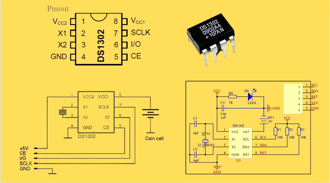
DS1302 RTC: Datasheet,Attributes,Features,Applications
As a low-power device widely used in electronic equipment, the DS1302 is centered on accurate real-time clock/calendar recording functions. It supports full-dimensional tracking of seconds, minutes, hours, days, weeks, months, and years, features automatic leap year compensation, and is compatible w...
-
2025 / 07 / 30
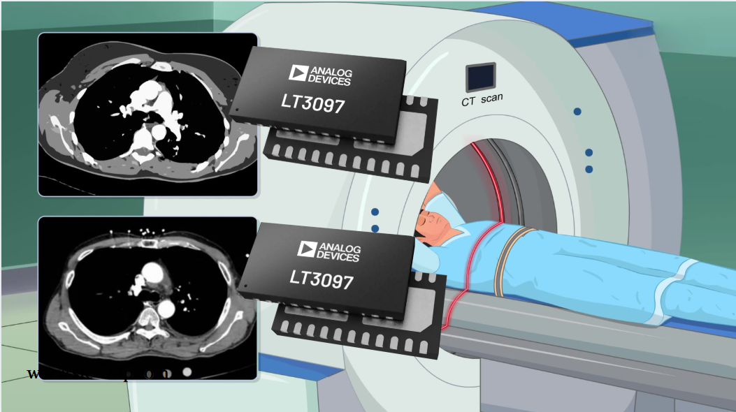
LT3097 Dual 500 mA, positive/negative, ultralow noise, ultrahigh PSRR low dropout linear regulator
The LT3097 is a dual, positive and negative, high-performance, low-dropout linear regulator featuring Analog Devices, Inc., ultralow noise and ultra-high power supply rejection ratio (PSRR) architecture for powering noise-sensitive applications. Each regulator delivers up to 500 mA with a typical 26...
-
2025 / 07 / 28
What is a Digital Integrated Circuit?
In the fast - paced world of modern electronics, digital integrated circuits (ICs) are the unsung heroes that power everything from our smartphones and laptops to complex supercomputers and industrial control systems. But what exactly is a digital integrated circuit?...
-
2025 / 07 / 25
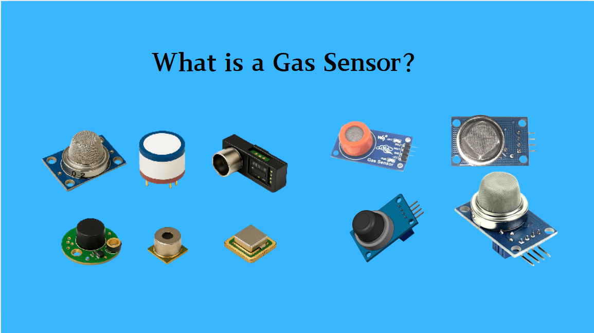
What is a Gas Sensor?
A gas sensor is a device that can convert information such as the composition and concentration of gas into electrical signals recognizable by electronic equipment. It is like the "olfactory organ" of an electronic system, capable of acutely detecting the presence of specific gases in the environmen...
-
2025 / 07 / 24
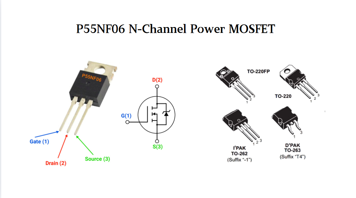
P55NF06 N-Channel Power MOSFET: Everything You Need To Know
In the vast landscape of semiconductor devices, MOSFETs (Metal - Oxide - Semiconductor Field - Effect Transistors) play a pivotal role, especially in power electronics. Among the numerous MOSFET models available, the P55NF06 stands out for its unique combination of features, making it suitable for a...
-
2025 / 07 / 23
Operational Amplifier Filters: A Comprehensive Analysis from Fundamentals to Applications
In electronic systems, the purity and accuracy of signals directly determine the performance of devices. Electronic filters composed of operational amplifiers (op-amps) have become a "bridge" connecting original signals and valid information, thanks to their ability to precisely filter signal freque...
-
2025 / 07 / 19
Broadcom BCM5714CKPB: Featrues,Applications,Datasheet And Advantages
When it comes to reliable, high-performance network connectivity in enterprise and industrial systems, the Broadcom BCM5714CKPB stands as a standout solution. This dual-port Gigabit Ethernet controller, developed by Broadcom—a leader in semiconductor innovation—combines robust features, versatile co...
-
2025 / 07 / 15
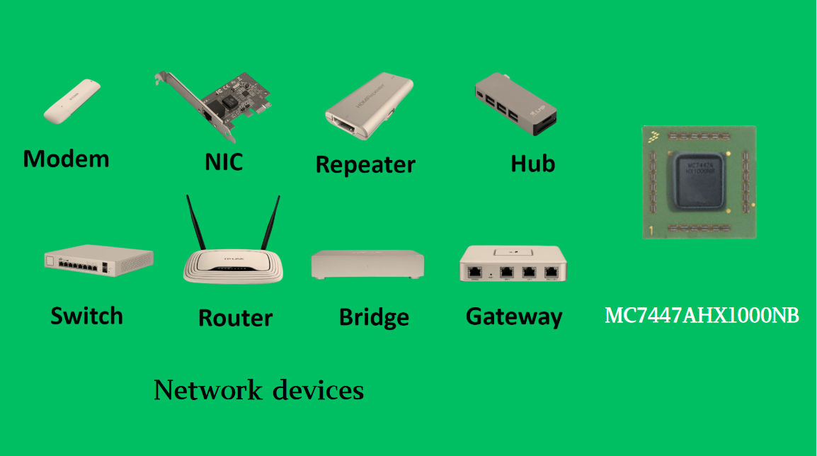
MC7447AHX1000NB: Technical Analysis and Applications of a High-Performance PowerPC Architecture Proc
In the field of embedded computing and network systems, the performance, energy efficiency, and compatibility of processors are often crucial to the success of a design. The MC7447AHX1000NB launched by NXP (formerly Freescale), as an important member of the MPC7447A series, has become an ideal choic...
-
2025 / 07 / 14
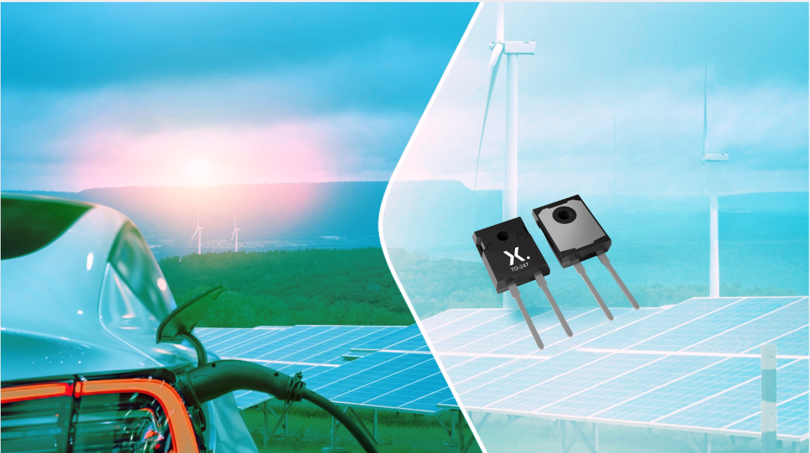
Nexperia Unveils New 1200V/20A SiC Schottky Diodes to Empower Efficient Industrial Power Innovations
Nexperia recently announced the addition of two new 1200V, 20A silicon carbide (SiC) Schottky diodes—PSC20120J and PSC20120L—to its power electronics portfolio, further expanding its product landscape in high-performance semiconductors. Specifically designed to address the increasingly stringent dem...
-
2025 / 07 / 09
CD4007: A Comprehensive Analysis of a Multifunctional CMOS Integrated Circuit
In the field of modern electronic technology, CMOS (Complementary Metal-Oxide-Semiconductor) integrated circuits have become core components in digital and analog circuit design due to their low power consumption, high integration, and excellent compatibility. As a classic CMOS device, the CD4007 oc...


2000+
Daily average RFQ Volume

30,000,000
Standard Product Unit

2800+
Worldwide Manufacturers

15,000 m2
In-stock Warehouse
 Wishlist (0 Items)