

- RFQ
- BOM
-
Contact Us
Tel: +86-0755-83501315
Email: sales@sic-components.com


- Chinese
- English
- French
- German
- Portuguese
- Spanish
- Russian
- Japanese
- Korean
- Arabic
- Irish
- Greek
- Turkish
- Italian
- Danish
- Romanian
- Indonesian
- Czech
- Afrikaans
- Swedish
- Polish
- Basque
- Catalan
- Esperanto
- Hindi
- Lao
- Albanian
- Amharic
- Armenian
- Azerbaijani
- Belarusian
- Bengali
- Bosnian
- Bulgarian
- Cebuano
- Chichewa
- Corsican
- Croatian
- Dutch
- Estonian
- Filipino
- Finnish
- Frisian
- Galician
- Georgian
- Gujarati
- Haitian
- Hausa
- Hawaiian
- Hebrew
- Hmong
- Hungarian
- Icelandic
- Igbo
- Javanese
- Kannada
- Kazakh
- Khmer
- Kurdish
- Kyrgyz
- Latin
- Latvian
- Lithuanian
- Luxembou..
- Macedonian
- Malagasy
- Malay
- Malayalam
- Maltese
- Maori
- Marathi
- Mongolian
- Burmese
- Nepali
- Norwegian
- Pashto
- Persian
- Punjabi
- Serbian
- Sesotho
- Sinhala
- Slovak
- Slovenian
- Somali
- Samoan
- Scots Gaelic
- Shona
- Sindhi
- Sundanese
- Swahili
- Tajik
- Tamil
- Telugu
- Thai
- Ukrainian
- Urdu
- Uzbek
- Vietnamese
- Welsh
- Xhosa
- Yiddish
- Yoruba
- Zulu
- Kinyarwanda
- Tatar
- Oriya
- Turkmen
- Uyghur
Gate Driver
Gate drivers are electronic circuits that are used to control the switching of power semiconductor devices, such as metal - oxide - semiconductor field - effect transistors (MOSFETs) and insulated - gate bipolar transistors (IGBTs). They play a crucial role in power electronics by providing the necessary drive signals to turn these devices on and off efficiently.
Features and Limits of Gate Drivers
Features
High - speed switching: Gate drivers are capable of providing fast - rising and fast - falling edge signals to the gate of the power device, enabling rapid switching between the on - state and off - state. This is essential for applications that require high - frequency operation, such as switching power supplies and motor drives.
Isolation: Many gate drivers offer electrical isolation between the control circuit and the power circuit. This isolation helps to protect the sensitive control electronics from the high voltages and currents present in the power stage, improving the reliability and safety of the overall system.
Current sourcing and sinking: They can source and sink sufficient current to charge and discharge the gate - to - source capacitance of the power device quickly. This ensures that the device turns on and off within the desired time intervals, minimizing power losses during the switching process.
Protection features: Gate drivers often come with built - in protection mechanisms, such as over - current protection, over - voltage protection, and short - circuit protection. These features help to safeguard the power device and the entire system from damage in the event of abnormal operating conditions.
Limits
Power handling capabilities: The maximum power that a gate driver can handle is limited by its internal components and packaging. Exceeding this limit can lead to overheating and potential failure of the gate driver.
Switching frequency limitations: Although gate drivers are designed for high - speed switching, there is an upper limit to the frequency at which they can operate reliably. At very high frequencies, parasitic effects such as capacitive and inductive coupling can cause signal distortion and reduced performance.
Voltage and current ratings: Gate drivers have specific voltage and current ratings that must be adhered to. Operating outside these ratings can result in improper operation of the power device or even damage to the gate driver itself.
The Role of Gate Drivers
Control of power devices: The primary role of a gate driver is to control the conduction state of power semiconductor devices. By applying the appropriate voltage signal to the gate terminal, the gate driver can turn the device on or off, allowing precise control of the power flow in a circuit.
Improving efficiency: Gate drivers ensure that the power devices switch on and off quickly and efficiently, minimizing the time spent in the transition region where significant power losses occur. This helps to improve the overall efficiency of power - conversion systems.
Signal conditioning: They condition the control signals from the microcontroller or other control circuitry to the appropriate level and format required by the power device. This includes amplifying the signal, shaping the waveform, and providing the necessary isolation.
Types of Gate Drivers
Bridge - type Drivers
Half - Bridge Drivers: These are designed for applications that require high - power uni - directional DC motors, three - phase brushless DC motors, or other inductive loads. They consist of two power switches connected in a half - bridge configuration, allowing for the control of the motor or load in one direction. Half - bridge drivers are commonly used in applications where cost - effectiveness and simplicity are important, such as in some industrial motor drives and low - to - medium - power switching power supplies.
Full - Bridge Drivers: A full - bridge controller is used with external N - channel power MOSFETs and is designed for automotive applications with high - power inductive loads. The full - bridge configuration allows for bidirectional control of the load, making it suitable for applications where the direction of current flow needs to be reversed, such as in electric vehicle drives and some high - power industrial applications. It provides better power - handling capabilities and more precise control compared to the half - bridge driver.
3 - Phase Drivers
Designed for pulse - width - modulated (PWM) current control of 3 - phase, brushless DC motors. They are used in applications where precise speed and torque control of the motor is required, such as in industrial automation, robotics, and some high - performance electric vehicle drives. 3 - phase drivers typically use advanced control algorithms to optimize the motor's performance and efficiency.
Piezoelectric Drivers
Piezoelectricity is the electricity that comes from pressure and latent heat. Piezoelectric drivers (or Piezo drivers) are gate drivers designed to support piezo components. This includes optical fibre, inkjet printers, microphones, speakers, and XY stages for micro - scanning used in infrared cameras. They provide the necessary high - voltage and high - frequency signals to drive the piezoelectric elements, enabling their precise operation in various applications.
Gate Driver Parameters
Output voltage and current: The output voltage and current ratings of a gate driver determine the maximum voltage and current that it can supply to the gate of the power device. These parameters must be carefully selected to match the requirements of the power device and the application.
Switching speed: The switching speed of a gate driver is characterized by the rise time and fall time of the output signal. Faster switching speeds are generally preferred for high - frequency applications to minimize power losses, but they also require more careful design and may be limited by the capabilities of the gate driver and the power device.
Isolation type and level: If the gate driver provides isolation, the type of isolation (such as magnetic or optical) and the isolation level (rated in volts) are important parameters. The isolation level must be sufficient to protect the control circuit from the high voltages in the power circuit.
Protection features: The presence and type of protection features, such as over - current, over - voltage, and short - circuit protection, are crucial considerations. These features can help to prevent damage to the power device and the gate driver in the event of faults.
Gate Driver ICs Selection Guide
Application requirements: The first step in selecting a gate driver IC is to consider the specific requirements of the application. This includes the type of power device being used (MOSFET, IGBT, etc.), the power level, the switching frequency, and the required protection features.
Device compatibility: Ensure that the gate driver IC is compatible with the power device in terms of voltage and current ratings, as well as gate - drive requirements. Some power devices may have specific requirements for the gate - drive signal, such as a certain voltage level or rise/fall time.
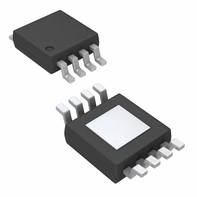
Package type and size: The package type and size of the gate driver IC should be suitable for the available space on the printed circuit board. Different package types offer different advantages in terms of thermal performance, electrical isolation, and ease of assembly.
Manufacturer and quality: Choose a gate driver IC from a reputable manufacturer with a proven track record of quality and reliability. This can help to ensure that the device will perform as expected and provide long - term stability in the application.
Integrated Drivers vs. Gate Drivers
Integrated Drivers: Integrated drivers typically combine the functions of a gate driver with other components, such as power switches, control circuitry, and sometimes even protection circuits, into a single integrated circuit. They offer a high level of integration, reducing the number of external components and simplifying the design process. Integrated drivers are often used in applications where space is limited and a high - level of functionality is required, such as in some consumer electronics and low - power industrial applications.
Gate Drivers: Gate drivers, on the other hand, focus specifically on providing the drive signals for power semiconductor devices. They are more modular and can be used in conjunction with external power switches and other components to build custom - tailored power - conversion systems. Gate drivers offer more flexibility in terms of power - handling capabilities and can be easily adapted to different types of power devices and applications. They are commonly used in high - power and high - performance applications where the specific requirements of the power stage need to be carefully optimized.
Difference between an IGBT and a MOSFET
Structure and operation: MOSFETs are voltage - controlled devices that operate based on the formation of a conductive channel between the source and drain terminals by applying a voltage to the gate. IGBTs, on the other hand, are a combination of a MOS - controlled input stage and a bipolar - transistor output stage. They offer the advantages of both MOSFETs (high - input impedance, fast switching) and bipolar transistors (low - on - state resistance, high - current handling capabilities).
Switching speed: MOSFETs generally have faster switching speeds than IGBTs, making them suitable for high - frequency applications. IGBTs, while not as fast as MOSFETs, have a lower on - state voltage drop, which results in lower power losses at high currents.
Power handling capabilities: IGBTs are typically better suited for high - power applications due to their ability to handle higher currents and voltages. MOSFETs are more commonly used in low - to - medium - power applications where fast switching speed is a priority.
Applications: MOSFETs are widely used in applications such as switching power supplies, audio amplifiers, and digital circuits. IGBTs are commonly used in high - power applications such as industrial motor drives, electric vehicle chargers, and power inverters for renewable energy systems.
Excellent Gate Driver ICs
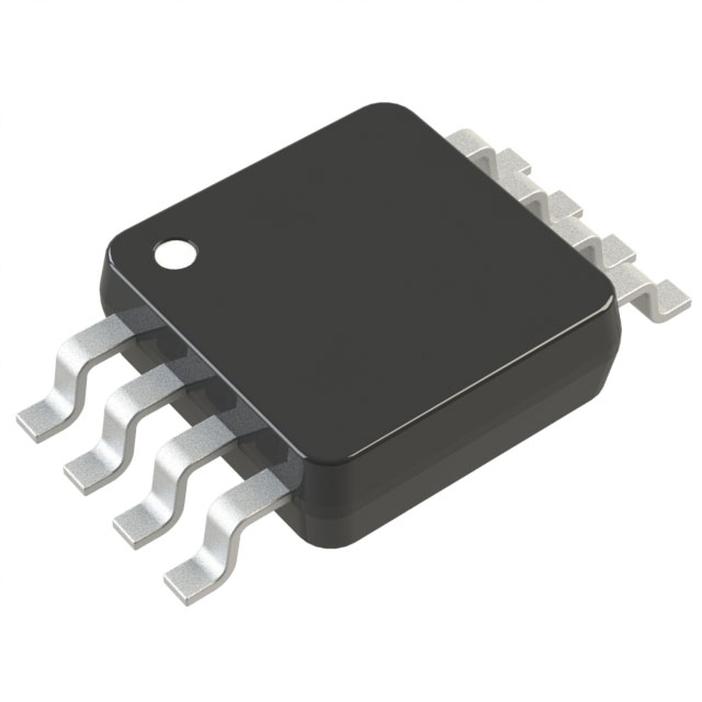
MCP1416T - E/OT (https://www.sic-components.com/product/product?product_id=1947978): Microchip Technology Low - side gate driver, single - channel, suitable for IGBTs, MOSFETs (N - channel, P - channel). Power supply voltage: 4.5V - 18V. Logic voltage: 0.8V, 2.4V. Peak output current: 1.5A, 1.5A. Non - inverting. Rise/fall time: 20ns, 20ns. Operating temperature: - 40°C - 150°C (TJ). Surface - mount, package: SOT - 23 - 5
MCP1402T - E/OT (https://www.sic-components.com/product/product?product_id=1679123): Microchip Technology Low - side gate driver, single - channel, suitable for IGBTs, MOSFETs (N - channel, P - channel). Power supply voltage: 4.5V - 18V. Logic voltage: 0.8V, 2.4V. Peak output current: 500mA, 500mA. Non - inverting. Rise/fall time: 19ns, 15ns. Operating temperature: - 40°C - 150°C (TJ). Surface - mount, package: SOT - 23 - 5
MCP1415T - E/OT(https://www.sic-components.com/product/product?product_id=1947977):Microchip Technology Low - side gate driver, single - channel, suitable for IGBTs, MOSFETs (N - channel, P - channel). Power supply voltage: 4.5V - 18V. Logic voltage: 0.8V, 2.4V. Peak output current: 1.5A, 1.5A. Inverting. Rise/fall time: 20ns, 20ns. Operating temperature: - 40°C - 150°C (TJ). Surface - mount, package: SOT - 23 - 5
MCP1401T - E/OT (https://www.sic-components.com/product/product?product_id=1679122 ): Microchip Technology Low - side gate driver, single - channel, suitable for IGBTs, MOSFETs (N - channel, P - channel). Power supply voltage: 4.5V - 18V. Logic voltage: 0.8V, 2.4V. Peak output current: 500mA, 500mA. Inverting. Rise/fall time: 19ns, 15ns. Operating temperature: - 40°C - 125°C. Surface - mount, package: SOT - 23 - 5
AP22816AKBWT - 7 (DGD0280WT - 7) (https://www.sic-components.com/product/product?product_id=16548004):Diodes Incorporated Low - side gate driver, single - channel, suitable for IGBTs, MOSFETs (N - channel, P - channel). Power supply voltage: 4.5V - 18V. Logic voltage: 0.8V, 2V. Peak output current: 2.5A, 2.8A. CMOS, TTL input types. Rise/fall time: 20ns, 15ns. Operating temperature: - 40°C - 125°C (TA). Surface - mount, package: TSOT - 23 - 5
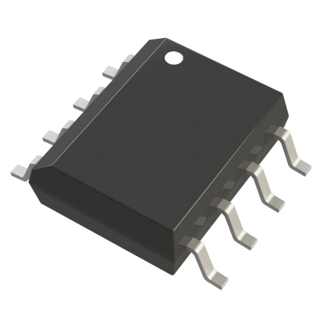
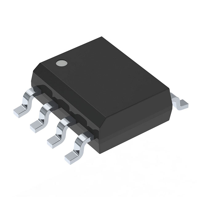
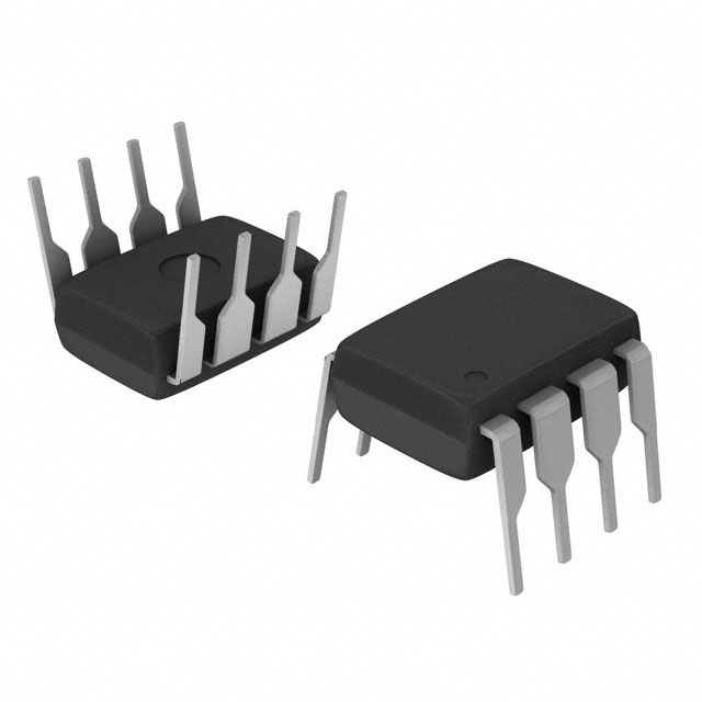
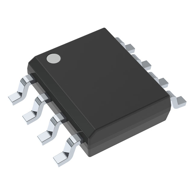
IR21271STRPBF (IRS2005STRPBF) (https://www.sic-components.com/product/product?product_id=812681 ): Infineon Technologies Half - bridge gate driver, independent channels, 2 drivers, suitable for IGBTs, MOSFETs (N - channel). Power supply voltage: 10V - 20V. Logic voltage: 0.8V, 2.5V. Peak output current: 290mA, 600mA. Non - inverting. Maximum high - side voltage: 200V. Rise/fall time: 70ns, 30ns. Operating temperature: - 40°C - 150°C (TJ). Surface - mount, package: 8 - SOIC
IRS25411STRPBF (IRS2008STRPBF) ( https://www.sic-components.com/product/product?product_id=2605762): Infineon Technologies Half - bridge gate driver, synchronous channels, 2 drivers, suitable for MOSFETs (N - channel). Power supply voltage: 10V - 20V. Logic voltage: 0.8V, 2.5V. Peak output current: 290mA, 600mA. Non - inverting. Maximum high - side voltage: 200V. Rise/fall time: 70ns, 30ns. Operating temperature: - 40°C - 150°C (TJ). Surface - mount, package: 8 - SOIC
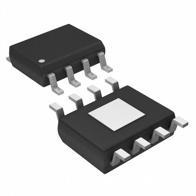
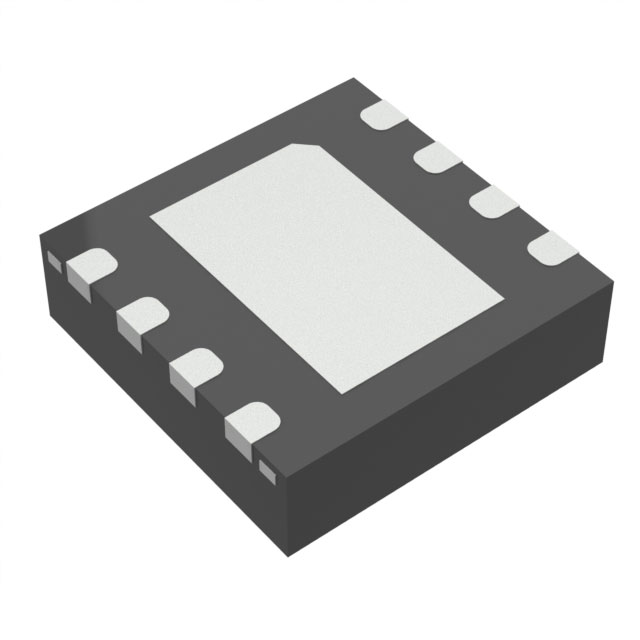
TLV2462AMDREP (LM5109BMAX/NOPB) ( https://www.sic-components.com/product/product?product_id=1629038): Texas Instruments Half - bridge gate driver, independent channels, 2 drivers, suitable for MOSFETs (N - channel). Power supply voltage: 8V - 14V. Logic voltage: 0.8V, 2.2V. Peak output current: 1A, 1A. Non - inverting. Maximum high - side voltage: 108V. Rise/fall time: 15ns, 15ns. Operating temperature: - 40°C - 125°C (TJ). Surface - mount, package: 8 - SOIC, also available in 4 - TQFN (1.2x1.2) package
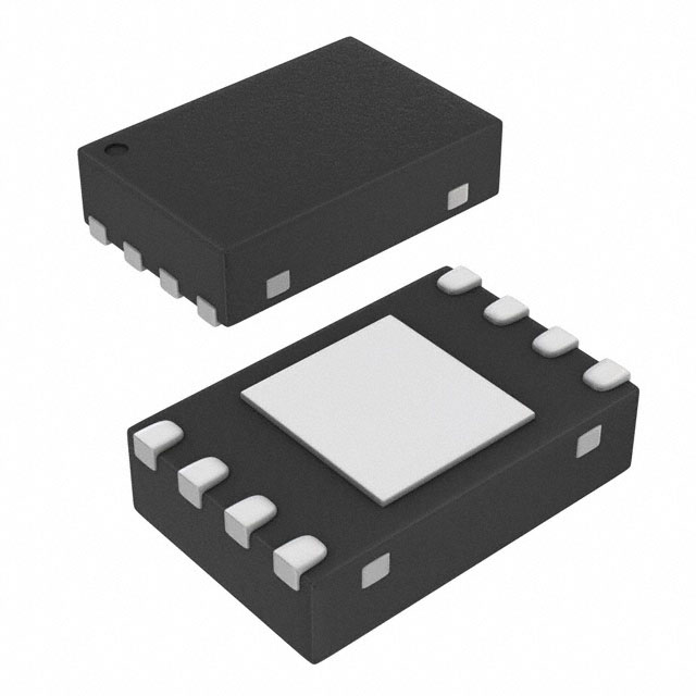
MIC4414YFT - TR( https://www.sic-components.com/product/product?product_id=5049083 ):Microchip Technology Low - side gate driver, single - channel, suitable for MOSFETs (N - channel). Power supply voltage: 4.5V - 18V. Logic voltage: 0.8V, 3V. Peak output current: 1.5A, 1.5A. Non - inverting. Rise/fall time: 12ns, 12ns. Operating temperature: - 40°C - 125°C (TJ). Surface - mount, package: 4 - TQFN (1.2x1.2), also available in 10 - VSON package
Information is from SIC Electronics Limited. If you are interested in the product or need product parameters, you can contact us online at any time or send us an email: sales@sic-components.com.
Hot Products
View More-
AUIRS4426S Infineon Technologies
-

UCC27525DGN Texas Instruments
-
IRS2332STRPBF Infineon Technologies
-
IR25603SPBF Infineon Technologies
-
ISL89161FBEAZ Renesas Electronics America Inc
-
FAN73933MX onsemi
-
IR2127 Infineon Technologies
-
ISL89163FRTAZ-T Renesas Electronics America Inc
-
MAX17604AUA+ Analog Devices Inc./Maxim Integrated
-
AUIRS2112S Infineon Technologies
-
TPS2813DR Texas Instruments
-
RT9624AZSP Richtek USA Inc.
Related Blogs
-
2025 / 08 / 01
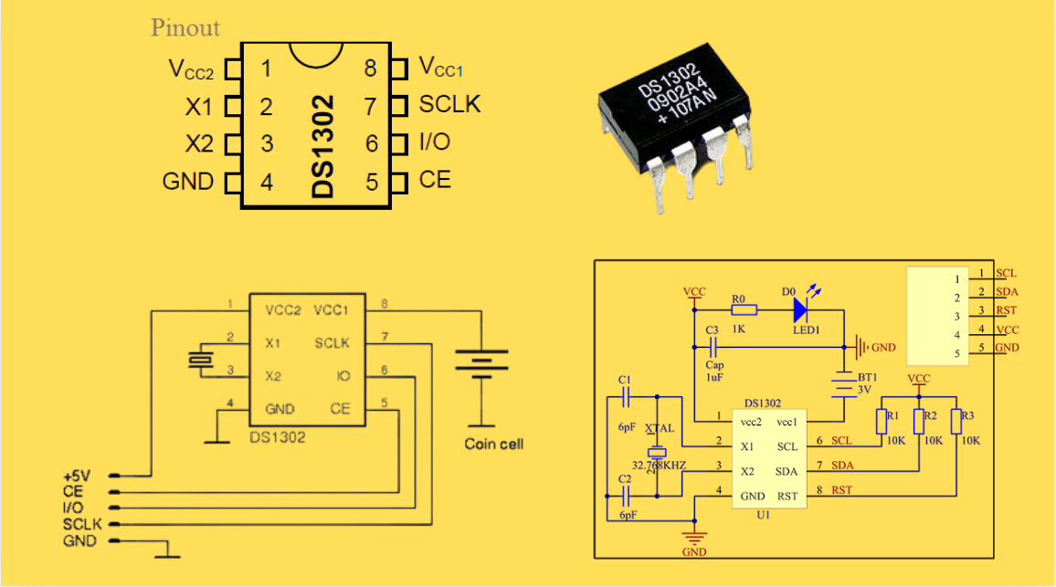
DS1302 RTC: Datasheet,Attributes,Features,Applications
As a low-power device widely used in electronic equipment, the DS1302 is centered on accurate real-time clock/calendar recording functions. It supports full-dimensional tracking of seconds, minutes, hours, days, weeks, months, and years, features automatic leap year compensation, and is compatible w...
-
2025 / 07 / 30
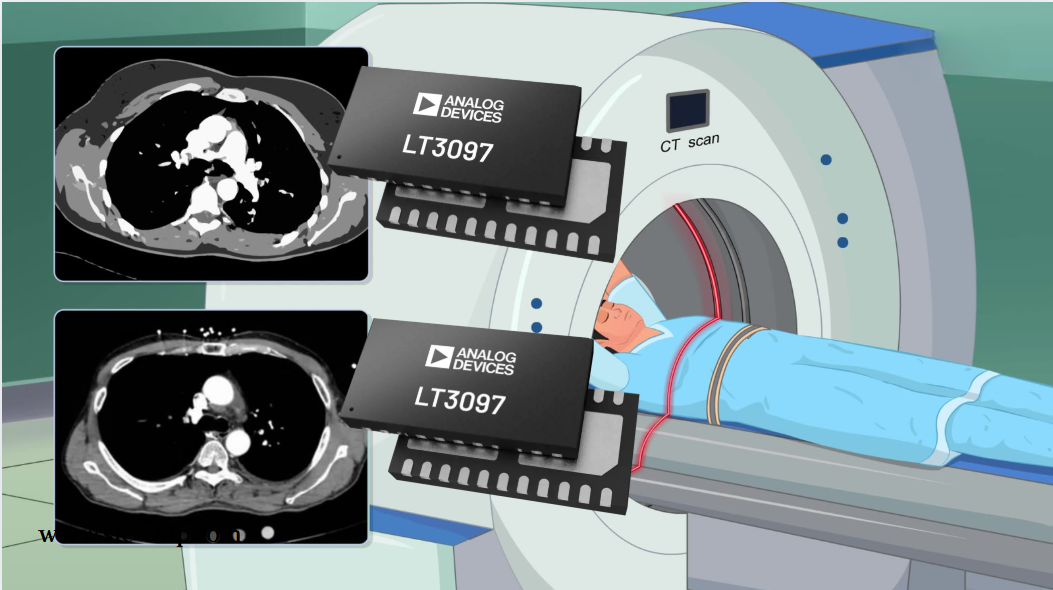
LT3097 Dual 500 mA, positive/negative, ultralow noise, ultrahigh PSRR low dropout linear regulator
The LT3097 is a dual, positive and negative, high-performance, low-dropout linear regulator featuring Analog Devices, Inc., ultralow noise and ultra-high power supply rejection ratio (PSRR) architecture for powering noise-sensitive applications. Each regulator delivers up to 500 mA with a typical 26...
-
2025 / 07 / 28
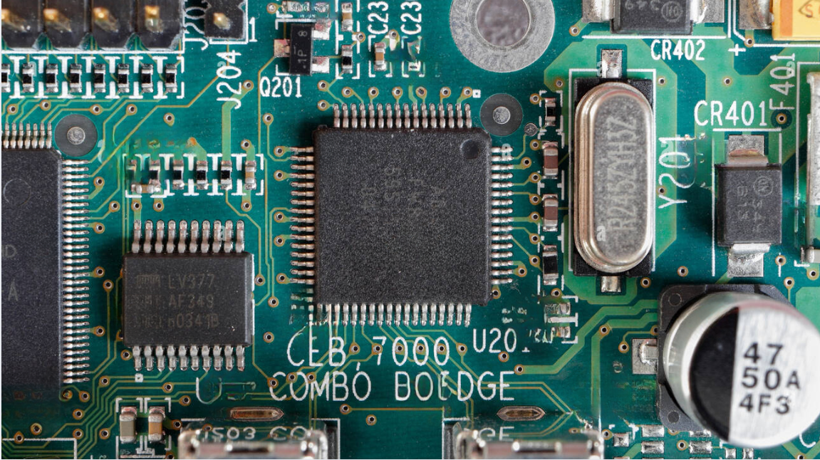
What is a Digital Integrated Circuit?
In the fast - paced world of modern electronics, digital integrated circuits (ICs) are the unsung heroes that power everything from our smartphones and laptops to complex supercomputers and industrial control systems. But what exactly is a digital integrated circuit?...
-
2025 / 07 / 25
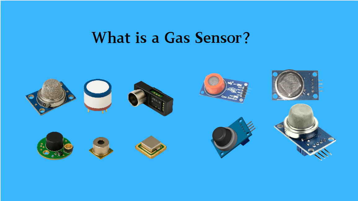
What is a Gas Sensor?
A gas sensor is a device that can convert information such as the composition and concentration of gas into electrical signals recognizable by electronic equipment. It is like the "olfactory organ" of an electronic system, capable of acutely detecting the presence of specific gases in the environmen...
-
2025 / 07 / 24
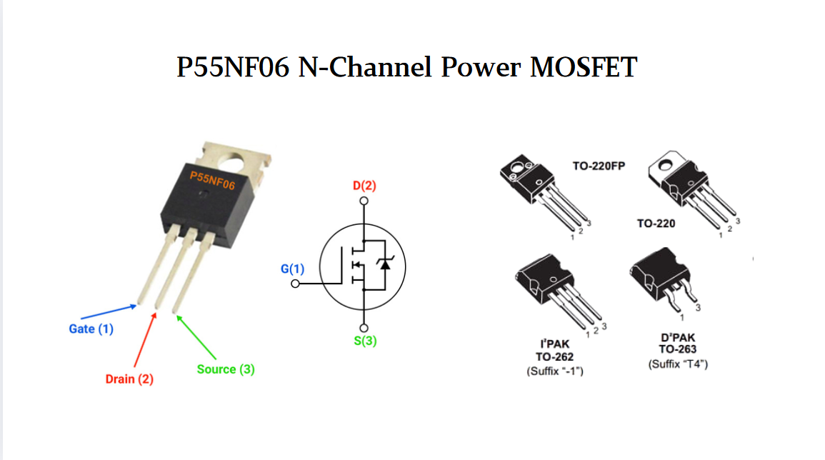
P55NF06 N-Channel Power MOSFET: Everything You Need To Know
In the vast landscape of semiconductor devices, MOSFETs (Metal - Oxide - Semiconductor Field - Effect Transistors) play a pivotal role, especially in power electronics. Among the numerous MOSFET models available, the P55NF06 stands out for its unique combination of features, making it suitable for a...
-
2025 / 07 / 23
Operational Amplifier Filters: A Comprehensive Analysis from Fundamentals to Applications
In electronic systems, the purity and accuracy of signals directly determine the performance of devices. Electronic filters composed of operational amplifiers (op-amps) have become a "bridge" connecting original signals and valid information, thanks to their ability to precisely filter signal freque...
-
2025 / 07 / 19
Broadcom BCM5714CKPB: Featrues,Applications,Datasheet And Advantages
When it comes to reliable, high-performance network connectivity in enterprise and industrial systems, the Broadcom BCM5714CKPB stands as a standout solution. This dual-port Gigabit Ethernet controller, developed by Broadcom—a leader in semiconductor innovation—combines robust features, versatile co...
-
2025 / 07 / 15
MC7447AHX1000NB: Technical Analysis and Applications of a High-Performance PowerPC Architecture Proc
In the field of embedded computing and network systems, the performance, energy efficiency, and compatibility of processors are often crucial to the success of a design. The MC7447AHX1000NB launched by NXP (formerly Freescale), as an important member of the MPC7447A series, has become an ideal choic...
-
2025 / 07 / 14
Nexperia Unveils New 1200V/20A SiC Schottky Diodes to Empower Efficient Industrial Power Innovations
Nexperia recently announced the addition of two new 1200V, 20A silicon carbide (SiC) Schottky diodes—PSC20120J and PSC20120L—to its power electronics portfolio, further expanding its product landscape in high-performance semiconductors. Specifically designed to address the increasingly stringent dem...
-
2025 / 07 / 09
CD4007: A Comprehensive Analysis of a Multifunctional CMOS Integrated Circuit
In the field of modern electronic technology, CMOS (Complementary Metal-Oxide-Semiconductor) integrated circuits have become core components in digital and analog circuit design due to their low power consumption, high integration, and excellent compatibility. As a classic CMOS device, the CD4007 oc...


2000+
Daily average RFQ Volume

30,000,000
Standard Product Unit

2800+
Worldwide Manufacturers

15,000 m2
In-stock Warehouse
 Wishlist (0 Items)