

- RFQ
- BOM
-
Contact Us
Tel: +86-0755-83501315
Email: sales@sic-components.com


- Chinese
- English
- French
- German
- Portuguese
- Spanish
- Russian
- Japanese
- Korean
- Arabic
- Irish
- Greek
- Turkish
- Italian
- Danish
- Romanian
- Indonesian
- Czech
- Afrikaans
- Swedish
- Polish
- Basque
- Catalan
- Esperanto
- Hindi
- Lao
- Albanian
- Amharic
- Armenian
- Azerbaijani
- Belarusian
- Bengali
- Bosnian
- Bulgarian
- Cebuano
- Chichewa
- Corsican
- Croatian
- Dutch
- Estonian
- Filipino
- Finnish
- Frisian
- Galician
- Georgian
- Gujarati
- Haitian
- Hausa
- Hawaiian
- Hebrew
- Hmong
- Hungarian
- Icelandic
- Igbo
- Javanese
- Kannada
- Kazakh
- Khmer
- Kurdish
- Kyrgyz
- Latin
- Latvian
- Lithuanian
- Luxembou..
- Macedonian
- Malagasy
- Malay
- Malayalam
- Maltese
- Maori
- Marathi
- Mongolian
- Burmese
- Nepali
- Norwegian
- Pashto
- Persian
- Punjabi
- Serbian
- Sesotho
- Sinhala
- Slovak
- Slovenian
- Somali
- Samoan
- Scots Gaelic
- Shona
- Sindhi
- Sundanese
- Swahili
- Tajik
- Tamil
- Telugu
- Thai
- Ukrainian
- Urdu
- Uzbek
- Vietnamese
- Welsh
- Xhosa
- Yiddish
- Yoruba
- Zulu
- Kinyarwanda
- Tatar
- Oriya
- Turkmen
- Uyghur
How does current flow through capacitor?
Abstract
This article delves deep into the intricate relationship between current and capacitors, exploring the physical phenomena that occur when current passes through them. It comprehensively analyzes the behavior of capacitors in direct - current (DC) and alternating - current (AC) circuits, elucidating the underlying principles of current flow, charging, discharging, and associated physical effects. Additionally, it introduces an advanced capacitor product designed to optimize electrical system performance, highlighting the practical significance of understanding capacitor - current interactions.
1. Introduction
In the realm of electronics, the capacitor stands as a fundamental and indispensable component, playing a pivotal role in a multitude of electrical and electronic systems. The interaction between current and capacitors triggers a series of complex and captivating physical phenomena, which are not only rooted in the basic principles of electrical circuits but also have far - reaching implications for various practical applications. A profound understanding of these phenomena is crucial for engineers and researchers to design optimized circuits, enhance the performance of electronic devices, and troubleshoot related technical issues.
When a current traverses a capacitor, one of the most prominent physical manifestations is the establishment and evolution of the electric field. The process commences with the capacitor's charging phase. Upon connection to a power source, charges begin to accumulate on the two conductor plates of the capacitor. Initially, with a minimal amount of charge on the plates, the electric field strength between them is relatively weak. As the charging process progresses, more and more charges are stored on the plates. According to the direct - proportional relationship between the electric field strength and the charge quantity on the plates, the electric field strength gradually intensifies. For example, in a simple DC charging circuit, as time elapses, the electric field strength between the capacitor plates steadily increases until the charging is complete, at which point the electric field strength reaches its peak value.
During the capacitor's discharging process, as the charges on the plates are released through an external circuit, the charge amount on the plates diminishes, and consequently, the electric field strength between the plates also weakens. The energy stored within the electric field is gradually converted into other forms of energy, such as heat energy and light energy when passing through a load. From the perspective of energy conservation, throughout the entire charging and discharging cycle, energy continuously undergoes conversion between electrical energy and electric field energy.
2. Current Flow Through Capacitors in Different Circuits
2.1 Direct - Current (DC) Circuits
2.1.1 Transient Current Flow
In a DC circuit, when a capacitor is first connected to a power source, an instantaneous charging current is generated. At the moment of connection, the electromotive force of the power source creates an electric field force that drives electrons to accumulate on one plate of the capacitor while simultaneously extracting electrons from the other plate. This occurs because, initially, the capacitor plates are uncharged, and the voltage across them is zero. The disparity between the power source voltage and the capacitor - plate voltage prompts the directional movement of charges, thereby forming a current.
2.1.2 Current Cessation
As the charging process advances, the charges on the capacitor plates continue to accumulate, and the voltage across the plates gradually rises. Once the voltage across the capacitor plates becomes equal to the power source voltage, the voltage difference disappears. At this point, the electric field force can no longer drive the charges to move directionally, and the charging current drops to zero, halting the current flow through the capacitor. From a microscopic perspective, when the voltages are equal, the electric field forces exerted by the capacitor plates on the electrons balance out the electric field force of the power source, eliminating the electrons' tendency for directional movement, which is macroscopically manifested as the cessation of current.
2.2 Alternating - Current (AC) Circuits
2.2.1 Continuous Current Flow
The voltage of an AC power source varies periodically in both magnitude and direction over time. When the AC power source voltage increases, the capacitor initiates the charging process, and current flows into the capacitor; conversely, when the voltage decreases, the capacitor discharges, and current flows out of the capacitor. Within a complete cycle, the capacitor undergoes continuous charging and discharging, enabling the continuous existence of current. Fundamentally, the AC power source constantly alters the voltage difference across the capacitor plates, ensuring that the charges always have a tendency for directional movement, thus generating a continuous current.
2.2.2 Mechanism of Current Flow
In an AC circuit, the current appears to "flow" through the capacitor via the capacitor's charging and discharging processes. When the power source voltage exceeds the voltage across the capacitor plates, the power source charges the capacitor, and charges flow from the power source to the capacitor plates. When the power source voltage is lower than the capacitor - plate voltage, the capacitor discharges into the circuit, and charges flow from the capacitor plates back to the circuit. Although charges do not actually pass through the insulating medium between the capacitor plates, an effect similar to current flowing through the capacitor is created in the circuit. The frequency of this charging - discharging cycle is identical to the frequency of the AC power source, effectively enabling the "flow" of alternating current through the capacitor.
3. Physical Phenomena Associated with Current Flow Through Capacitors
3.1 Charging and Discharging
During the charging process, current enters the capacitor, leading to the accumulation of charges on the capacitor plates. The voltage across the plates gradually increases until it matches the power supply voltage. In the discharging process, the charges on the capacitor plates are released through the external circuit, and current flows out of the capacitor, causing the voltage across the plates to gradually decrease. Throughout these processes, the magnitude of the current in the circuit changes over time. The current gradually diminishes during charging and gradually increases during discharging.
3.2 Electric Field Dynamics
As the capacitor charges, the accumulation of charges on the plates establishes an electric field between them. The strength of this electric field is directly proportional to the amount of charge on the plates. The electric field strength increases during charging and weakens during discharging, and the associated electric field energy changes accordingly, increasing during charging and decreasing during discharging. The electric field energy is stored within the electric field between the capacitor plates.
3.3 Heating Effect
In practical capacitors, there exists a certain equivalent series resistance. When current passes through this resistance, heat is generated according to Joule's law, resulting in the heating of the capacitor. Additionally, dielectric loss also converts a portion of the electrical energy into heat energy, further increasing the capacitor's temperature. Prolonged passage of a relatively large current may cause the capacitor to overheat, which can negatively impact its performance and even lead to damage.
3.4 Electromagnetic Interference
At the instant when current flows through the capacitor, especially in high - frequency circuits, rapidly changing electric and magnetic fields are generated, potentially causing electromagnetic interference (EMI). This EMI can have detrimental effects on surrounding electronic devices, leading to issues such as signal distortion and unstable device operation.
3.5 Polarization Phenomenon
For certain electrolytic capacitors, polarization occurs when current flows through them. A thin oxide film forms on the electrode surface, serving as the dielectric. Due to the polarization effect, the positive and negative poles of the capacitor must be connected correctly; otherwise, the oxide film may be damaged, resulting in a decline in the capacitor's performance or even its failure.
4. Product Introduction: Advanced Capacitor And Current Solution
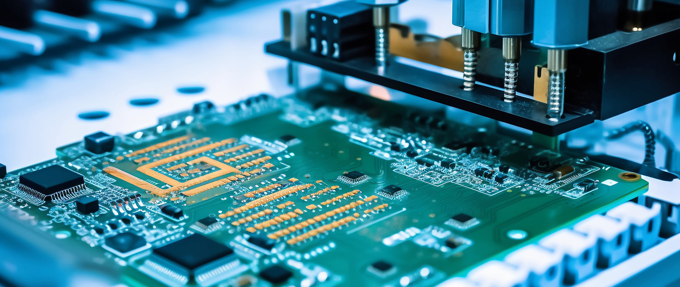
To meet the evolving demands of modern electrical systems, we are proud to introduce our advanced Capacitor And Current product. Engineered with cutting - edge technology, this capacitor is designed to store and release electrical energy with high efficiency, facilitating a smooth and stable current flow that is essential for the optimal performance of diverse electrical applications.
Constructed with high - quality materials, our capacitor offers reliable performance across a wide range of industries, including power distribution, electric vehicles, renewable energy, and more. It is specifically designed to improve the power factor, reduce energy consumption, and enhance the overall efficiency of electrical systems.
Our commitment to quality and innovation ensures that the Capacitor And Current product is a vital component for any electrical system aiming to achieve a stable and reliable power supply. With its advanced technology and durable construction, it can withstand the rigorous demands of modern electrical applications, providing long - lasting and stable performance.
Experience the difference with our Capacitor And Current product and unlock the benefits of a seamless and efficient current flow in your electrical systems.
5. Conclusion
The flow of current through capacitors is a complex yet fascinating subject, encompassing a variety of physical phenomena and principles. Understanding how capacitors behave in DC and AC circuits, as well as the associated physical effects, is essential for the design, operation, and maintenance of electronic systems. The introduction of our advanced capacitor product further emphasizes the practical importance of these concepts, offering a solution to enhance the performance of electrical systems. As technology continues to evolve, in - depth research and exploration of capacitor - current interactions will undoubtedly drive further innovation in the field of electronics.
https://www.sic-components.com/capacitors


Hot Products
View More


Related Blogs
-
2025 / 08 / 01
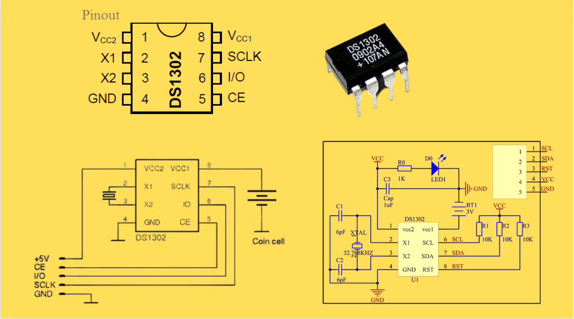
DS1302 RTC: Datasheet,Attributes,Features,Applications
As a low-power device widely used in electronic equipment, the DS1302 is centered on accurate real-time clock/calendar recording functions. It supports full-dimensional tracking of seconds, minutes, hours, days, weeks, months, and years, features automatic leap year compensation, and is compatible w...
-
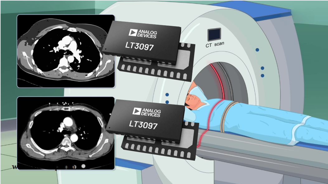
2025 / 07 / 30
LT3097 Dual 500 mA, positive/negative, ultralow noise, ultrahigh PSRR low dropout linear regulator
The LT3097 is a dual, positive and negative, high-performance, low-dropout linear regulator featuring Analog Devices, Inc., ultralow noise and ultra-high power supply rejection ratio (PSRR) architecture for powering noise-sensitive applications. Each regulator delivers up to 500 mA with a typical 26...
-
2025 / 07 / 28
What is a Digital Integrated Circuit?
In the fast - paced world of modern electronics, digital integrated circuits (ICs) are the unsung heroes that power everything from our smartphones and laptops to complex supercomputers and industrial control systems. But what exactly is a digital integrated circuit?...
-
2025 / 07 / 25
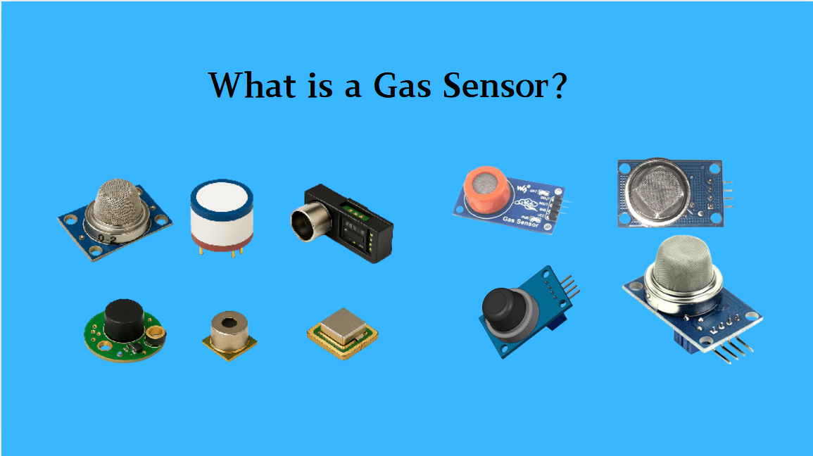
What is a Gas Sensor?
A gas sensor is a device that can convert information such as the composition and concentration of gas into electrical signals recognizable by electronic equipment. It is like the "olfactory organ" of an electronic system, capable of acutely detecting the presence of specific gases in the environmen...
-
2025 / 07 / 24
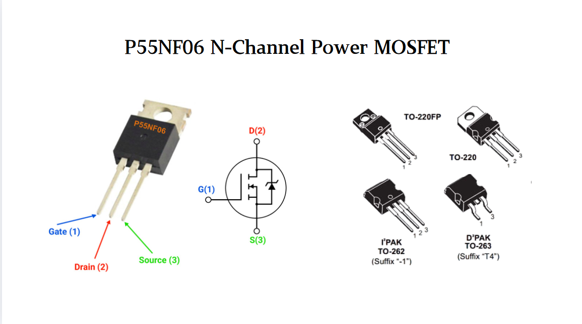
P55NF06 N-Channel Power MOSFET: Everything You Need To Know
In the vast landscape of semiconductor devices, MOSFETs (Metal - Oxide - Semiconductor Field - Effect Transistors) play a pivotal role, especially in power electronics. Among the numerous MOSFET models available, the P55NF06 stands out for its unique combination of features, making it suitable for a...
-
2025 / 07 / 23
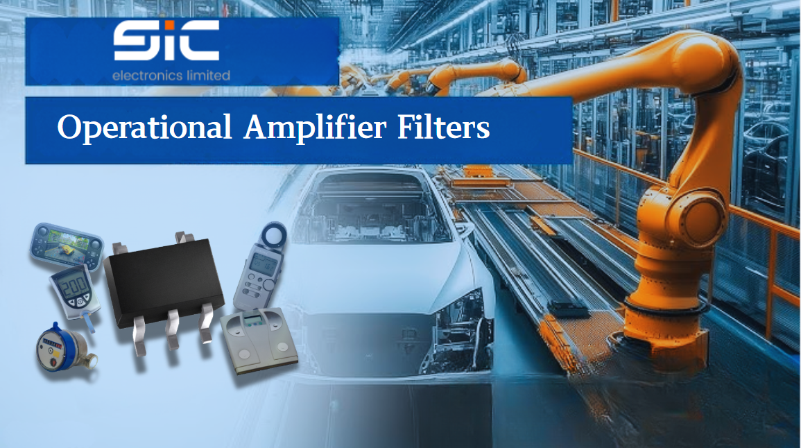
Operational Amplifier Filters: A Comprehensive Analysis from Fundamentals to Applications
In electronic systems, the purity and accuracy of signals directly determine the performance of devices. Electronic filters composed of operational amplifiers (op-amps) have become a "bridge" connecting original signals and valid information, thanks to their ability to precisely filter signal freque...
-
2025 / 07 / 19
Broadcom BCM5714CKPB: Featrues,Applications,Datasheet And Advantages
When it comes to reliable, high-performance network connectivity in enterprise and industrial systems, the Broadcom BCM5714CKPB stands as a standout solution. This dual-port Gigabit Ethernet controller, developed by Broadcom—a leader in semiconductor innovation—combines robust features, versatile co...

-
2025 / 07 / 15
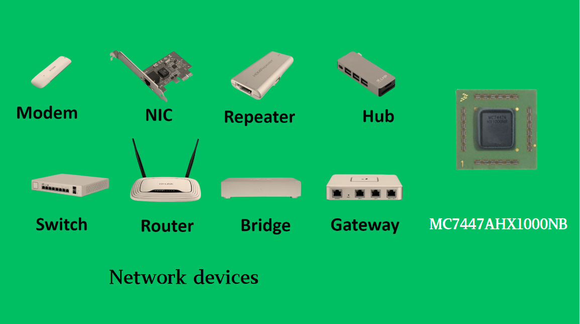
MC7447AHX1000NB: Technical Analysis and Applications of a High-Performance PowerPC Architecture Proc
In the field of embedded computing and network systems, the performance, energy efficiency, and compatibility of processors are often crucial to the success of a design. The MC7447AHX1000NB launched by NXP (formerly Freescale), as an important member of the MPC7447A series, has become an ideal choic...
-
2025 / 07 / 14
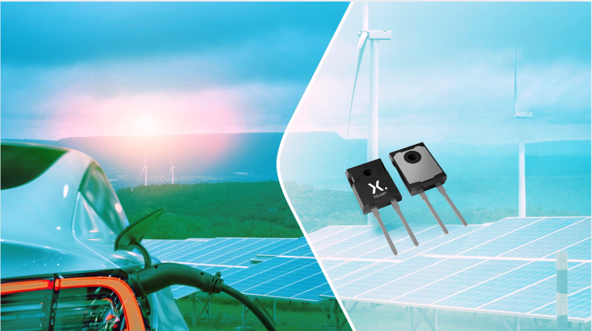
Nexperia Unveils New 1200V/20A SiC Schottky Diodes to Empower Efficient Industrial Power Innovations
Nexperia recently announced the addition of two new 1200V, 20A silicon carbide (SiC) Schottky diodes—PSC20120J and PSC20120L—to its power electronics portfolio, further expanding its product landscape in high-performance semiconductors. Specifically designed to address the increasingly stringent dem...
-
2025 / 07 / 09
CD4007: A Comprehensive Analysis of a Multifunctional CMOS Integrated Circuit
In the field of modern electronic technology, CMOS (Complementary Metal-Oxide-Semiconductor) integrated circuits have become core components in digital and analog circuit design due to their low power consumption, high integration, and excellent compatibility. As a classic CMOS device, the CD4007 oc...


2000+
Daily average RFQ Volume

30,000,000
Standard Product Unit

2800+
Worldwide Manufacturers

15,000 m2
In-stock Warehouse
 Wishlist (0 Items)