

- RFQ
- BOM
-
Contact Us
Tel: +86-0755-83501315
Email: sales@sic-components.com


- Chinese
- English
- French
- German
- Portuguese
- Spanish
- Russian
- Japanese
- Korean
- Arabic
- Irish
- Greek
- Turkish
- Italian
- Danish
- Romanian
- Indonesian
- Czech
- Afrikaans
- Swedish
- Polish
- Basque
- Catalan
- Esperanto
- Hindi
- Lao
- Albanian
- Amharic
- Armenian
- Azerbaijani
- Belarusian
- Bengali
- Bosnian
- Bulgarian
- Cebuano
- Chichewa
- Corsican
- Croatian
- Dutch
- Estonian
- Filipino
- Finnish
- Frisian
- Galician
- Georgian
- Gujarati
- Haitian
- Hausa
- Hawaiian
- Hebrew
- Hmong
- Hungarian
- Icelandic
- Igbo
- Javanese
- Kannada
- Kazakh
- Khmer
- Kurdish
- Kyrgyz
- Latin
- Latvian
- Lithuanian
- Luxembou..
- Macedonian
- Malagasy
- Malay
- Malayalam
- Maltese
- Maori
- Marathi
- Mongolian
- Burmese
- Nepali
- Norwegian
- Pashto
- Persian
- Punjabi
- Serbian
- Sesotho
- Sinhala
- Slovak
- Slovenian
- Somali
- Samoan
- Scots Gaelic
- Shona
- Sindhi
- Sundanese
- Swahili
- Tajik
- Tamil
- Telugu
- Thai
- Ukrainian
- Urdu
- Uzbek
- Vietnamese
- Welsh
- Xhosa
- Yiddish
- Yoruba
- Zulu
- Kinyarwanda
- Tatar
- Oriya
- Turkmen
- Uyghur
How to increase amplifier stability?
Figuring out how to increase amplifier stability—well, it’s not just about adding a capacitor here or a resistor there. It’s about understanding why amplifiers oscillate or become unstable in the first place. Most of the time, it’s a feedback loop issue. Amplifiers rely on negative feedback to set gain and linearity, but if that feedback signal gets delayed or phase-shifted just enough, it can turn into positive feedback. And positive feedback? That’s when things start to ring, or oscillate, or just behave unpredictably.
Let me start with the basics: layout. I’ve seen so many designs fail because the PCB traces were a mess. Long input leads, especially for high-frequency signals, act like antennas, picking up noise that gets fed back into the loop. Keep the input and output traces short, separate them if you can, so the output doesn’t couple back into the input. Ground planes help—a solid, continuous ground plane under the amplifier can reduce parasitic inductance and capacitance, which are big culprits for phase shifts. I once fixed a 100MHz amplifier that kept oscillating by simply moving the feedback resistor closer to the IC pins. The original layout had the resistor an inch away, creating a small loop that acted like an inductor. Shortening that trace made the oscillation stop.
Then there’s compensation. Most op amps come with internal compensation, designed to be stable for unity gain, but if you’re using them in a higher gain configuration, or with capacitive loads, that might not be enough. Adding a small capacitor in the feedback path—maybe 10pF to 100pF—can roll off the high-frequency gain, preventing the phase shift from reaching 180 degrees (that’s the point where negative feedback becomes positive). But you have to be careful not to overdo it. Too much compensation slows down the amplifier, making it sluggish for fast signals. It’s a balance—between stability and bandwidth. I tend to start with the datasheet’s recommended compensation values, then tweak from there.
Capacitive loads are another headache. A long cable, a big capacitor at the output—they add phase lag, which can destabilize the loop. Some amplifiers have built-in output current limiting or snubber circuits to handle this, but if yours doesn’t, adding a small series resistor (like 50 ohms) between the amplifier output and the capacitive load can isolate it. The resistor dampens the resonance between the amplifier’s output impedance and the load capacitance. It’s a simple fix, though it does reduce gain slightly. Better than an oscillating output, though.
Power supply decoupling is something people overlook, I think. Amplifiers draw current in pulses, especially when switching, and if the power supply can’t respond quickly, it creates voltage dips that get fed back into the circuit. A good decoupling capacitor—100nF ceramic, placed as close to the IC’s power pins as possible—provides a local energy source, smoothing out those pulses. For high-power amplifiers, a larger electrolytic capacitor (1µF to 10µF) in parallel can help with lower-frequency fluctuations. I’ve seen amplifiers stabilize instantly after adding proper decoupling—no other changes needed. It’s amazing how much noise a bad power supply can inject.
Gain setting matters too. Amplifiers are more stable at higher gains, generally. At unity gain (gain = 1), the phase margin is often the smallest, making them more prone to oscillation. If you can design your circuit to run at a higher gain—say, 10 instead of 1—you might avoid stability issues altogether. Of course, that’s not always possible, but it’s worth considering. Sometimes adding a small amount of positive gain in the feedback network (carefully) can improve phase margin, though that’s a trickier adjustment and easy to mess up.
Temperature plays a role, too. Components change with heat—resistors drift, capacitors change value, the amplifier’s own parameters shift. An amplifier that’s stable at 25°C might oscillate when it’s hot. That’s why it’s important to test stability over the full operating temperature range, not just on your bench. I’ve had to rework circuits because they passed cold tests but failed when heated up. It’s a hassle, but skipping it can lead to field failures.
At the end of the day, increasing amplifier stability is about managing phase shifts in the feedback loop. Every component, every trace, every connection adds some phase lag—your job is to keep that lag small enough that negative feedback stays negative. It’s not always straightforward, and there’s a lot of trial and error involved. But once you get a feel for how each part affects the loop—how a capacitor here or a resistor there changes the response—it gets easier. And honestly, there’s a certain satisfaction in taming an unruly amplifier, getting it to behave exactly as it should.
https://www.sic-components.com

Hot Products
View More-

78359-0111 Molex
-
126B-190A00 ATTEND Technology
-
10148733-0301P13LF Amphenol ICC (FCI)
-
10079248-10207LF Amphenol ICC (FCI)
-
10151386-0300J13LF Amphenol ICC (FCI)
-
10145891-0101K13LF Amphenol ICC (FCI)
-
0879400001 Molex
-
0783780003 Molex
-
10124677-0301F13LF Amphenol ICC (FCI)
-
10136688-1011103LF Amphenol ICC (FCI)
-
10152217-0302J11LF Amphenol ICC (FCI)
-
10141972-1201N13LF Amphenol ICC (FCI)
Related Blogs
-
2025 / 08 / 01
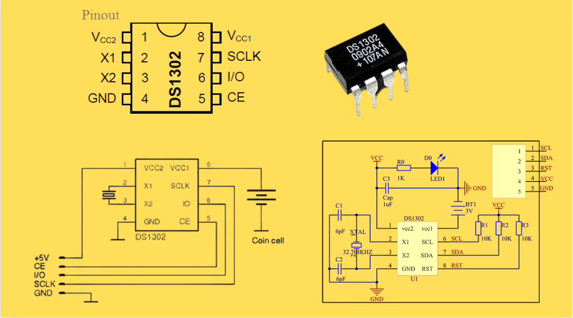
DS1302 RTC: Datasheet,Attributes,Features,Applications
As a low-power device widely used in electronic equipment, the DS1302 is centered on accurate real-time clock/calendar recording functions. It supports full-dimensional tracking of seconds, minutes, hours, days, weeks, months, and years, features automatic leap year compensation, and is compatible w...
-
2025 / 07 / 30
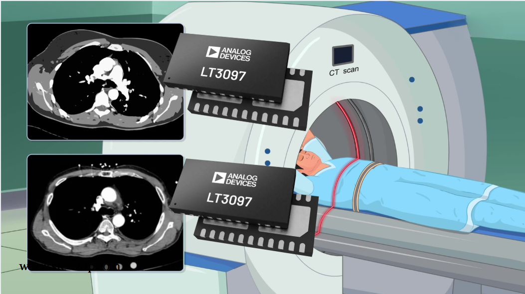
LT3097 Dual 500 mA, positive/negative, ultralow noise, ultrahigh PSRR low dropout linear regulator
The LT3097 is a dual, positive and negative, high-performance, low-dropout linear regulator featuring Analog Devices, Inc., ultralow noise and ultra-high power supply rejection ratio (PSRR) architecture for powering noise-sensitive applications. Each regulator delivers up to 500 mA with a typical 26...
-
2025 / 07 / 28
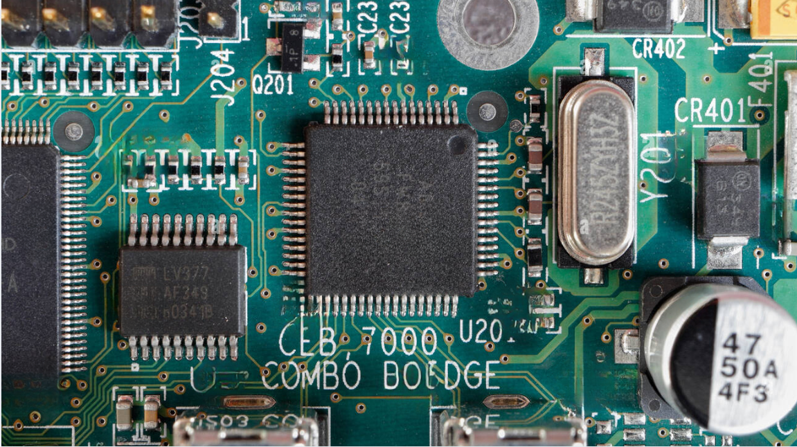
What is a Digital Integrated Circuit?
In the fast - paced world of modern electronics, digital integrated circuits (ICs) are the unsung heroes that power everything from our smartphones and laptops to complex supercomputers and industrial control systems. But what exactly is a digital integrated circuit?...
-
2025 / 07 / 25
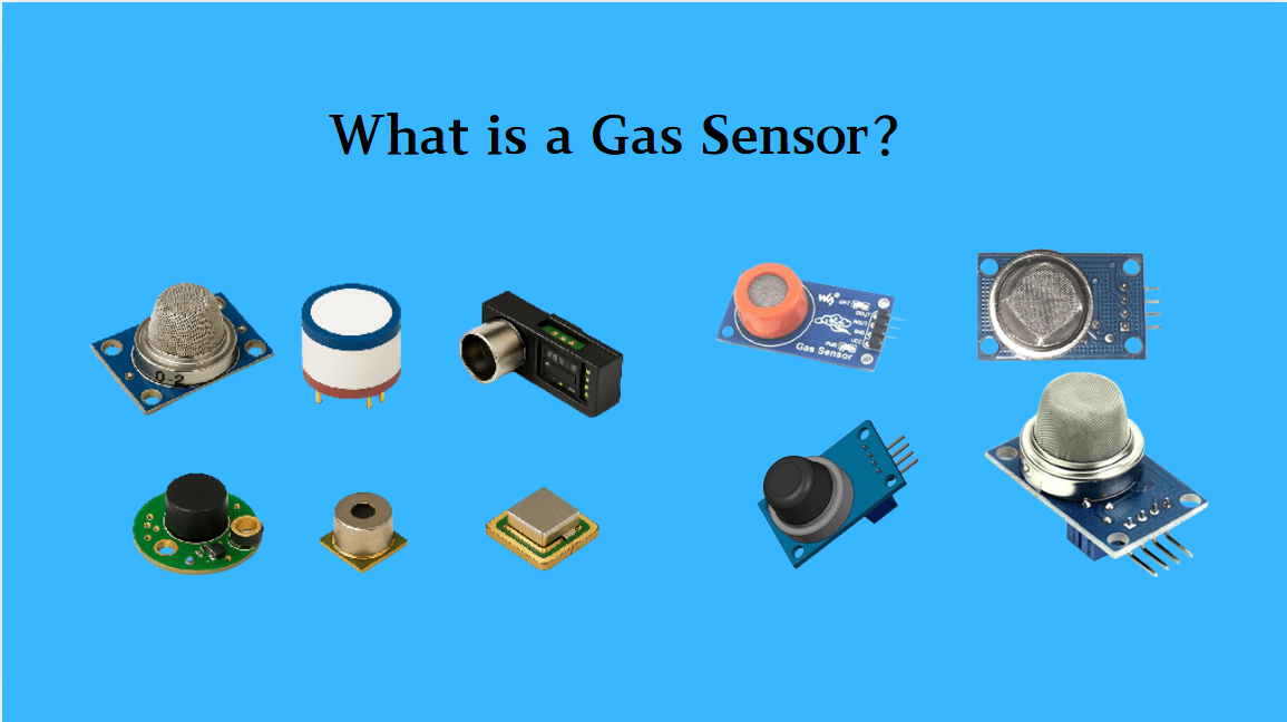
What is a Gas Sensor?
A gas sensor is a device that can convert information such as the composition and concentration of gas into electrical signals recognizable by electronic equipment. It is like the "olfactory organ" of an electronic system, capable of acutely detecting the presence of specific gases in the environmen...
-
2025 / 07 / 24
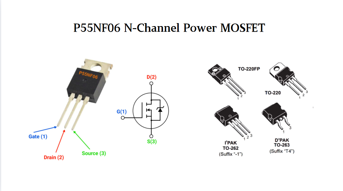
P55NF06 N-Channel Power MOSFET: Everything You Need To Know
In the vast landscape of semiconductor devices, MOSFETs (Metal - Oxide - Semiconductor Field - Effect Transistors) play a pivotal role, especially in power electronics. Among the numerous MOSFET models available, the P55NF06 stands out for its unique combination of features, making it suitable for a...
-
2025 / 07 / 23
Operational Amplifier Filters: A Comprehensive Analysis from Fundamentals to Applications
In electronic systems, the purity and accuracy of signals directly determine the performance of devices. Electronic filters composed of operational amplifiers (op-amps) have become a "bridge" connecting original signals and valid information, thanks to their ability to precisely filter signal freque...
-
2025 / 07 / 19
Broadcom BCM5714CKPB: Featrues,Applications,Datasheet And Advantages
When it comes to reliable, high-performance network connectivity in enterprise and industrial systems, the Broadcom BCM5714CKPB stands as a standout solution. This dual-port Gigabit Ethernet controller, developed by Broadcom—a leader in semiconductor innovation—combines robust features, versatile co...

-
2025 / 07 / 15
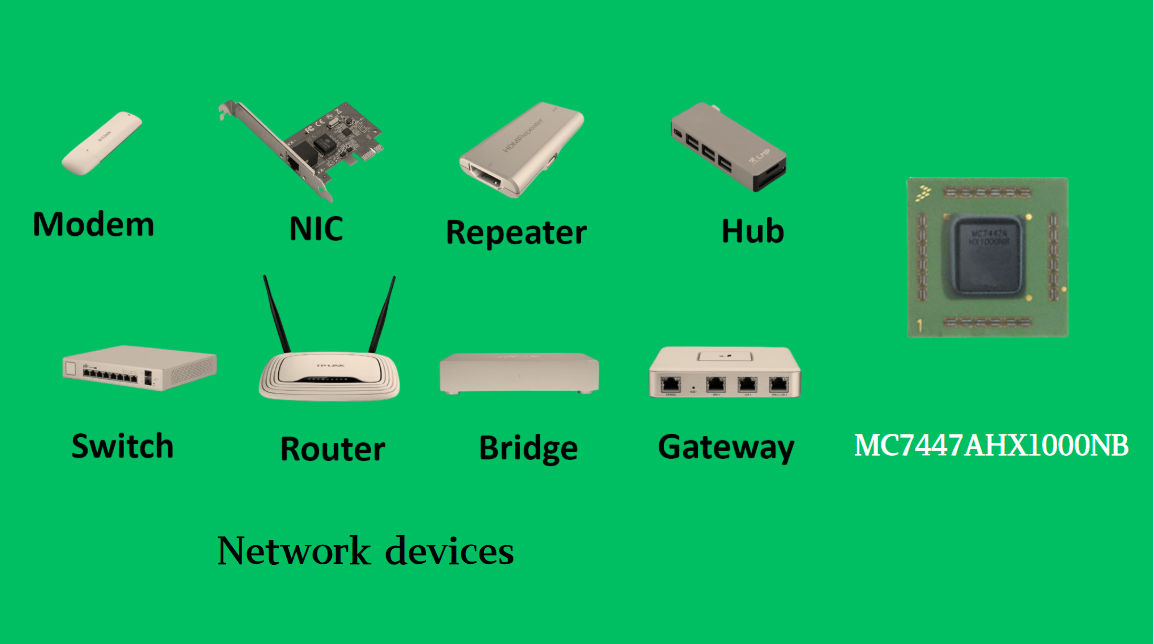
MC7447AHX1000NB: Technical Analysis and Applications of a High-Performance PowerPC Architecture Proc
In the field of embedded computing and network systems, the performance, energy efficiency, and compatibility of processors are often crucial to the success of a design. The MC7447AHX1000NB launched by NXP (formerly Freescale), as an important member of the MPC7447A series, has become an ideal choic...
-
2025 / 07 / 14
Nexperia Unveils New 1200V/20A SiC Schottky Diodes to Empower Efficient Industrial Power Innovations
Nexperia recently announced the addition of two new 1200V, 20A silicon carbide (SiC) Schottky diodes—PSC20120J and PSC20120L—to its power electronics portfolio, further expanding its product landscape in high-performance semiconductors. Specifically designed to address the increasingly stringent dem...

-
2025 / 07 / 09
CD4007: A Comprehensive Analysis of a Multifunctional CMOS Integrated Circuit
In the field of modern electronic technology, CMOS (Complementary Metal-Oxide-Semiconductor) integrated circuits have become core components in digital and analog circuit design due to their low power consumption, high integration, and excellent compatibility. As a classic CMOS device, the CD4007 oc...


2000+
Daily average RFQ Volume

30,000,000
Standard Product Unit

2800+
Worldwide Manufacturers

15,000 m2
In-stock Warehouse
 Wishlist (0 Items)