

- RFQ
- BOM
-
Contact Us
Tel: +86-0755-83501315
Email: sales@sic-components.com


- Chinese
- English
- French
- German
- Portuguese
- Spanish
- Russian
- Japanese
- Korean
- Arabic
- Irish
- Greek
- Turkish
- Italian
- Danish
- Romanian
- Indonesian
- Czech
- Afrikaans
- Swedish
- Polish
- Basque
- Catalan
- Esperanto
- Hindi
- Lao
- Albanian
- Amharic
- Armenian
- Azerbaijani
- Belarusian
- Bengali
- Bosnian
- Bulgarian
- Cebuano
- Chichewa
- Corsican
- Croatian
- Dutch
- Estonian
- Filipino
- Finnish
- Frisian
- Galician
- Georgian
- Gujarati
- Haitian
- Hausa
- Hawaiian
- Hebrew
- Hmong
- Hungarian
- Icelandic
- Igbo
- Javanese
- Kannada
- Kazakh
- Khmer
- Kurdish
- Kyrgyz
- Latin
- Latvian
- Lithuanian
- Luxembou..
- Macedonian
- Malagasy
- Malay
- Malayalam
- Maltese
- Maori
- Marathi
- Mongolian
- Burmese
- Nepali
- Norwegian
- Pashto
- Persian
- Punjabi
- Serbian
- Sesotho
- Sinhala
- Slovak
- Slovenian
- Somali
- Samoan
- Scots Gaelic
- Shona
- Sindhi
- Sundanese
- Swahili
- Tajik
- Tamil
- Telugu
- Thai
- Ukrainian
- Urdu
- Uzbek
- Vietnamese
- Welsh
- Xhosa
- Yiddish
- Yoruba
- Zulu
- Kinyarwanda
- Tatar
- Oriya
- Turkmen
- Uyghur
series parallel circuit calculator
1. Basic Concepts and Calculations of Series Resistance https://www.sic-components.com/category-all
In the realm of electronics, series resistance is a fundamental concept. A series circuit is formed when multiple resistors are connected end - to - end in a continuous chain, creating a single path for the electric current to flow. Just like beads on a string, each resistor in a series circuit shares one electrical node with its adjacent resistor.
The defining characteristic of a series circuit is that the same amount of current passes through every component in the circuit. This is because there is only one route for the electrons to travel. Mathematically, the total resistance (Rtotal) of a series circuit is calculated by simply adding up the individual resistance values of all the resistors in the circuit. The formula is as follows: Rtotal=R1+R2+R3 +⋯+Rn, where R1,R2 ,R3 ,⋯,R n are the resistances of the individual resistors. For example, if we have three resistors with values R1=2Ω, R2 =3Ω, and R3 =5Ω connected in series, the total resistance of the circuit is Rtotal =2+3+5=10Ω. As more resistors are added in series, the total resistance of the circuit increases, which in turn causes the current flowing through the circuit to decrease according to Ohm's law ( I= V/R, where I is current, V is voltage, and R is resistance). This property makes series resistors useful for controlling current in a circuit, such as in a simple flashlight circuit where a resistor may be used to limit the current flowing through the bulb to prevent it from burning out.
2. Basic Concepts and Calculations of Parallel Resistance https://www.sic-components.com/category-all
In contrast to series circuits, parallel circuits offer a different configuration for resistors. In a parallel circuit, multiple resistors are connected such that their leads are linked across each other, creating multiple paths for the electric current to flow. In a purely parallel circuit, regardless of the number of components, there are always only two sets of electrically common points.
The key characteristic of a parallel circuit is that the voltage across each component is the same. However, the current splits and flows through each resistor depending on its resistance value. The total resistance (Rtotal) of a parallel circuit is calculated using the following formula: 1/Rtotal=1/(R1+R2+R3+⋯+Rn) For example, if we have two resistors R1=4Ω and R2=4Ω in parallel, we first calculate 1/Rtotal=1/4+1/4=2/4=1/2.
Then, by taking the reciprocal, we find that R total=2Ω. Notice that the total resistance of a parallel combination is always less than the resistance of any individual resistor in the circuit. This property is exploited in circuits where an increase in current flow is required, such as in power distribution systems where multiple components need to draw current from a common voltage source.
3. Steps to Use the Series Resistance Calculator https://www.sic-components.com/category-all
Step 1: Determine the Number of Resistors
The first step in using a series resistance calculator is to accurately count the number of resistors that are connected in series in your circuit. This may seem straightforward, but in complex circuits, it's important to double - check to ensure an accurate count.
Step 2: Enter the Value of Each Resistor
Open the series resistor calculator, which is available both as online tools and as functions in many electronics design software. Then, enter the resistance value of each resistor one by one. Most calculators allow you to choose from different units, such as ohms (Ω), kilohms (kΩ), or megaohms (MΩ). Make sure to enter the values precisely, as any error in input can lead to incorrect results.
Step 3: View the Calculation Results
After entering all the resistor values, click the calculate button. The calculator will then instantly display the total resistance value of the series circuit. This quick calculation helps designers and engineers verify if the circuit's resistance meets their design requirements, saving significant time compared to manual calculations.
4. Steps to Use the Parallel Resistance Calculator https://www.sic-components.com/category-all
Step 1: Determine the Number of Resistors
Similar to using the series resistance calculator, the initial step for the parallel resistance calculator is to determine the number of resistors connected in parallel in your circuit. Carefully analyze the circuit diagram or physical setup to get an accurate count.
Step 2: Enter the Value of Each Resistor
Access the parallel resistance calculator and enter the resistance value of each resistor in the designated fields. Pay close attention to the units of measurement and ensure that all values are entered correctly.
Step 3: View the Calculation Results
Once all the resistor values are entered, click the calculate button. The calculator will apply the parallel resistance formula and display the total resistance value of the parallel circuit. Given the complexity of the parallel resistance formula, using a calculator greatly reduces the risk of human - calculation errors.
5. How to Calculate Resistors in Series and Parallel? https://www.sic-components.com/category-all
When dealing with circuits that have a combination of series and parallel resistors, the key is to break down the circuit into smaller, more manageable parts. First, identify all the series and parallel sections within the circuit. Calculate the equivalent resistance of each series and parallel sub - section using the formulas mentioned earlier.
For example, if you have a circuit where two resistors Ra and Rb are in series, and this combination is in parallel with a third resistor Rc. First, calculate the equivalent resistance of the series part (Rab=Ra+Rb). Then, use the parallel resistance formula to find the total resistance of the circuit, with Rab and Rc as the two resistors in the parallel calculation: 1/Rtotal=1/Rab+1/Rc. Repeat this process of simplifying sections until you have calculated the overall equivalent resistance of the entire circuit.
6. What is the Difference Between Series and Parallel Circuits? https://www.sic-components.com/category-all
Connection Configuration: In a series circuit, components are connected end - to - end, forming a single continuous path for current flow. In a parallel circuit, components are connected across each other, creating two sets of electrically common points and multiple paths for current.
Current Flow: In series circuits, the same current passes through every component. In parallel circuits, the total current splits, with different amounts of current flowing through each branch depending on the resistance of the components in that branch.
Voltage Distribution: In series circuits, the total voltage is divided among the components based on their resistance values. In parallel circuits, the voltage across each component is the same as the voltage of the source.
Total Resistance: In series circuits, the total resistance is the sum of the individual resistances, and it increases as more resistors are added. In parallel circuits, the total resistance is calculated using the reciprocal formula and is always less than the resistance of the smallest individual resistor.
7. Application Scenarios and Precautions https://www.sic-components.com/category-all
Application Scenarios
Series Circuits: Series circuits are commonly used in applications where current limiting is required. For example, in LED lighting circuits, a series resistor is often used to limit the current flowing through the LED to prevent it from being damaged by excessive current. They are also used in voltage - dividing circuits, where different voltage levels are needed at various points in the circuit.
Parallel Circuits: Parallel circuits are widely used in power distribution systems. For instance, in household electrical wiring, all the electrical appliances are connected in parallel to the main power supply. This ensures that each appliance receives the same voltage and can operate independently without affecting the others. Parallel circuits are also used in amplifier circuits to provide multiple paths for current, which helps in improving the performance and stability of the amplifier.
Precautions
Accurate Resistance Values: When calculating resistances, whether manually or using a calculator, it is crucial to ensure that the resistance values of the components are accurate. Resistors may have a tolerance level, and in precision circuits, this tolerance needs to be considered. When entering values into a calculator, double - check that the values match the actual resistors used in the circuit.
Unit Consistency: In parallel resistance calculations, in particular, it is essential to ensure that all resistance values are in the same unit. Mixing units can lead to incorrect results. For example, if one resistor value is in ohms and another is in kilohms, convert them to the same unit before performing the calculation.
8. More Resistor Calculators https://www.sic-components.com/category-all
Ohms Law Calculator - to calculate resistance, current, voltage, and power.
SMD Resistor Code Calculator - to determine the value of any SMD resistor with 3 or 4 digit code.
Resistor Color Code Calculator - to find the tolerance and resistance values for through hole resistors with 4, 5 and 6 band color codes.
Series and Parallel Capacitor Calculator - to calculate the total capacitance of several capacitors connected in series or parallel.
Circuit Current Calculator - A perfect resistor current calculator to calculate the current flowing through each of the circuit's branches.
9. Frequently Asked Questions https://www.sic-components.com/category-all
Q: What happens if one resistor fails in a series circuit?
A: In a series circuit, if one resistor fails (for example, it burns out and creates an open circuit), the entire circuit is interrupted, and no current will flow through any of the components. This is because there is only one path for the current, and the break in one resistor stops the flow.
Q: What happens if one resistor fails in a parallel circuit?
A: In a parallel circuit, if one resistor fails (opens up), the other resistors will still function. The total resistance of the circuit will increase slightly, and the current through the remaining resistors will adjust according to Ohm's law. However, the voltage across the remaining resistors will remain the same as the source voltage.
Q: Can I use any resistor in a series or parallel circuit?
A: When choosing resistors for a circuit, you need to consider factors such as the power rating, tolerance, and the required resistance value. The power rating of the resistor should be sufficient to handle the power dissipated in the circuit to prevent overheating and damage. The tolerance determines how close the actual resistance value is to the nominal value, and in precision circuits, a lower - tolerance resistor may be required.
https://www.sic-components.com/category-all


Hot Products
View More

Related Blogs
-
2025 / 08 / 01
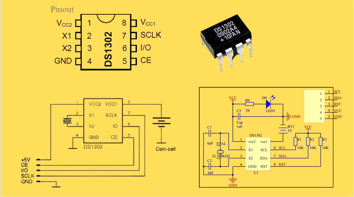
DS1302 RTC: Datasheet,Attributes,Features,Applications
As a low-power device widely used in electronic equipment, the DS1302 is centered on accurate real-time clock/calendar recording functions. It supports full-dimensional tracking of seconds, minutes, hours, days, weeks, months, and years, features automatic leap year compensation, and is compatible w...
-
2025 / 07 / 30
LT3097 Dual 500 mA, positive/negative, ultralow noise, ultrahigh PSRR low dropout linear regulator
The LT3097 is a dual, positive and negative, high-performance, low-dropout linear regulator featuring Analog Devices, Inc., ultralow noise and ultra-high power supply rejection ratio (PSRR) architecture for powering noise-sensitive applications. Each regulator delivers up to 500 mA with a typical 26...

-
2025 / 07 / 28
What is a Digital Integrated Circuit?
In the fast - paced world of modern electronics, digital integrated circuits (ICs) are the unsung heroes that power everything from our smartphones and laptops to complex supercomputers and industrial control systems. But what exactly is a digital integrated circuit?...
-
2025 / 07 / 25
What is a Gas Sensor?
A gas sensor is a device that can convert information such as the composition and concentration of gas into electrical signals recognizable by electronic equipment. It is like the "olfactory organ" of an electronic system, capable of acutely detecting the presence of specific gases in the environmen...

-
2025 / 07 / 24
P55NF06 N-Channel Power MOSFET: Everything You Need To Know
In the vast landscape of semiconductor devices, MOSFETs (Metal - Oxide - Semiconductor Field - Effect Transistors) play a pivotal role, especially in power electronics. Among the numerous MOSFET models available, the P55NF06 stands out for its unique combination of features, making it suitable for a...

-
2025 / 07 / 23
Operational Amplifier Filters: A Comprehensive Analysis from Fundamentals to Applications
In electronic systems, the purity and accuracy of signals directly determine the performance of devices. Electronic filters composed of operational amplifiers (op-amps) have become a "bridge" connecting original signals and valid information, thanks to their ability to precisely filter signal freque...

-
2025 / 07 / 19
Broadcom BCM5714CKPB: Featrues,Applications,Datasheet And Advantages
When it comes to reliable, high-performance network connectivity in enterprise and industrial systems, the Broadcom BCM5714CKPB stands as a standout solution. This dual-port Gigabit Ethernet controller, developed by Broadcom—a leader in semiconductor innovation—combines robust features, versatile co...

-
2025 / 07 / 15
MC7447AHX1000NB: Technical Analysis and Applications of a High-Performance PowerPC Architecture Proc
In the field of embedded computing and network systems, the performance, energy efficiency, and compatibility of processors are often crucial to the success of a design. The MC7447AHX1000NB launched by NXP (formerly Freescale), as an important member of the MPC7447A series, has become an ideal choic...

-
2025 / 07 / 14
Nexperia Unveils New 1200V/20A SiC Schottky Diodes to Empower Efficient Industrial Power Innovations
Nexperia recently announced the addition of two new 1200V, 20A silicon carbide (SiC) Schottky diodes—PSC20120J and PSC20120L—to its power electronics portfolio, further expanding its product landscape in high-performance semiconductors. Specifically designed to address the increasingly stringent dem...

-
2025 / 07 / 09
CD4007: A Comprehensive Analysis of a Multifunctional CMOS Integrated Circuit
In the field of modern electronic technology, CMOS (Complementary Metal-Oxide-Semiconductor) integrated circuits have become core components in digital and analog circuit design due to their low power consumption, high integration, and excellent compatibility. As a classic CMOS device, the CD4007 oc...


2000+
Daily average RFQ Volume

30,000,000
Standard Product Unit

2800+
Worldwide Manufacturers

15,000 m2
In-stock Warehouse
 Wishlist (0 Items)