

- RFQ
- BOM
-
Contact Us
Tel: +86-0755-83501315
Email: sales@sic-components.com


- Chinese
- English
- French
- German
- Portuguese
- Spanish
- Russian
- Japanese
- Korean
- Arabic
- Irish
- Greek
- Turkish
- Italian
- Danish
- Romanian
- Indonesian
- Czech
- Afrikaans
- Swedish
- Polish
- Basque
- Catalan
- Esperanto
- Hindi
- Lao
- Albanian
- Amharic
- Armenian
- Azerbaijani
- Belarusian
- Bengali
- Bosnian
- Bulgarian
- Cebuano
- Chichewa
- Corsican
- Croatian
- Dutch
- Estonian
- Filipino
- Finnish
- Frisian
- Galician
- Georgian
- Gujarati
- Haitian
- Hausa
- Hawaiian
- Hebrew
- Hmong
- Hungarian
- Icelandic
- Igbo
- Javanese
- Kannada
- Kazakh
- Khmer
- Kurdish
- Kyrgyz
- Latin
- Latvian
- Lithuanian
- Luxembou..
- Macedonian
- Malagasy
- Malay
- Malayalam
- Maltese
- Maori
- Marathi
- Mongolian
- Burmese
- Nepali
- Norwegian
- Pashto
- Persian
- Punjabi
- Serbian
- Sesotho
- Sinhala
- Slovak
- Slovenian
- Somali
- Samoan
- Scots Gaelic
- Shona
- Sindhi
- Sundanese
- Swahili
- Tajik
- Tamil
- Telugu
- Thai
- Ukrainian
- Urdu
- Uzbek
- Vietnamese
- Welsh
- Xhosa
- Yiddish
- Yoruba
- Zulu
- Kinyarwanda
- Tatar
- Oriya
- Turkmen
- Uyghur
What is a Chip On Board?
In the rapidly evolving electronics industry, where miniaturization and efficiency are highly pursued, Chip On Board (COB) technology has emerged as a revolutionary force. This technology has not only transformed the way electronic components are assembled but also opened up new possibilities for various applications, positioning itself as a key player in modern electronics manufacturing.
1. The Essence of Chip On Board
A Chip On Board printed circuit board represents an innovative packaging approach. Unlike conventional methods that involve mounting individual packaged components on a board, COB directly connects bare integrated circuits to the surface of the PCB. By bypassing traditional packaging techniques such as ceramic or plastic casings, COB enables the creation of smaller, lighter electronic devices and projects. This direct connection significantly reduces the overall size and weight of the final product, making it highly suitable for applications where space is at a premium.
2. The Evolution of COB Technology
The history of COB technology is intertwined with the development of the electronics industry. In the late 1950s, the invention of integrated circuits laid the foundation for component miniaturization. In the 1960s and 1970s, driven by the need to cut costs and save space, electronics manufacturers began exploring the direct attachment of integrated circuits to PCBs, giving birth to the early forms of COB technology. Initially, it was mainly used in low - end products like calculators and electronic toys.
During the 1980s and 1990s, as semiconductor manufacturing technology advanced, COB processes matured. Improvements in wire bonding technology increased the accuracy and reliability of connections, while enhancements in encapsulating materials further protected the chips. These advancements allowed COB technology to expand into new areas such as LED lighting and radio - frequency applications. In LED lighting, COB enabled the integration of multiple LED chips on a single board, improving luminous efficiency and heat dissipation. In RF systems, the elimination of lead frames reduced lead lengths, enhancing circuit performance.
Since the 21st century, with the continuous trend of miniaturization in electronic products, COB has become widely adopted. It is now commonly used in mobile phones, smart cards, and other miniaturized devices. Additionally, the development of related technologies like flip - chip COB has further broadened its application scope, especially in high - brightness LED lighting and high - performance electronic device packaging.
3. Applications of COB Technology
3.1 Lighting Applications
In the lighting industry, COB technology has brought about a revolution. It allows for the creation of more concentrated and powerful light sources by densely packing multiple LED chips onto a single board. This is particularly beneficial for commercial lighting in large spaces such as warehouses and supermarkets, where bright and even illumination is required. The compact design of COB - based lighting modules also makes them suitable for space - constrained installations like recessed ceiling lights.
Moreover, COB's excellent thermal and power efficiency is a significant advantage. LEDs generate heat during operation, and COB's good thermal conductivity ensures that the heat is effectively dissipated, maintaining the optimal operating temperature of the LEDs and extending their lifespan. The high power efficiency of COB also means lower energy consumption and cost savings. Additionally, COB enables more precise control of light output, facilitating the implementation of advanced lighting features such as dimming and color adjustment, making it ideal for architectural, stage, and retail display lighting.
3.2 RF Circuits
RF circuits face unique challenges due to the sensitivity of RF signals to component and connection properties. COB technology offers significant benefits in this area. By eliminating the lead frame, COB reduces the length of electrical connections, minimizing parasitic effects that can distort RF signals. This results in improved signal integrity and reduced signal loss, allowing RF circuits to operate more efficiently.
COB also enables a more compact and integrated design for RF circuits. In applications like wireless communication devices and radar systems, where space is limited, COB allows for the integration of multiple RF components on a single board. This simplifies the circuit layout and makes it easier to optimize RF performance. Additionally, the close proximity of the chip to the board in a COB configuration enables more effective shielding and grounding, reducing electromagnetic interference and ensuring the reliable operation of RF devices.
3.3 Cheap Integrated Circuits
COB technology has become increasingly popular in the production of affordable integrated circuits, especially in the consumer electronics market. One of the main reasons is cost savings. By eliminating traditional chip packaging, which involves additional materials, manufacturing steps, and assembly costs, COB offers a more cost - effective manufacturing solution. This is particularly important for mass - market products such as calculators, LCD displays, and electronic toys, where cost is a key factor in product competitiveness.
COB also provides design flexibility, allowing manufacturers to customize integrated circuits according to specific product requirements. This enables the creation of unique and tailored circuits that can meet the needs of different applications. Furthermore, the smaller size of COBs compared to traditionally packaged chips allows for more components to be packed into a smaller space, facilitating the miniaturization of electronic products.
3.4 Aerospace Engineering
Aerospace engineering has strict requirements for components, such as high reliability, low weight, and the ability to withstand harsh environments. COB technology meets these demands effectively. By reducing the number of components and connections, COB minimizes the risk of failure, which is crucial in aerospace applications where component failure can have catastrophic consequences. For example, in avionics systems, COB can be used to integrate critical components, ensuring stable and reliable operation during flight.
The compact and lightweight nature of COBs is also highly beneficial in aerospace. Every gram of weight saved can improve the fuel efficiency and performance of aircraft or space vehicles. Additionally, COBs can be designed to withstand extreme temperatures, high levels of vibration, and radiation, making them suitable for use in various onboard systems of satellites and other aerospace vehicles.
4. Advantages and Limitations of COB Assembly
4.1 Advantages
Weight Reduction: COB significantly reduces the weight of circuits, making it an ideal choice when weight is a major consideration.
Enhanced Protection: It offers better protection against reverse engineering.
Cost - effective: By eliminating traditional packaging, COB reduces manufacturing costs.
Improved Performance: Minimizing interconnection resistance and length improves electrical performance.
Space - saving: Its compact design requires minimal space on the circuit board.
Faster Time to Market: The streamlined assembly process can shorten the product development cycle.
Reliability: More uniform heat distribution and fewer solder joints contribute to higher reliability.
Versatility: COB has a wide range of applications across different industries.
4.2 Limitations
High Maintenance Cost: The maintenance cost of COB LED packaging is relatively high, and the qualification rate is low.
Expensive Manufacturing: Due to a high defect rate, the manufacturing cost of COB is higher than that of Surface Mount Device (SMD).
Color Uniformity: In some cases, the color uniformity of COB - based displays is not as good as traditional displays.
5. The Making of Chip On Board
5.1 Substrate Preparation
The process begins with preparing the PCB board. The surface of the board is cleaned, and an adhesive layer of conductive material is applied to the areas where the chips will be bonded. This ensures a strong and reliable connection between the chip and the board.
5.2 Die Attach
Bare chips are then positioned on the adhesive - coated areas of the board. Specialized pick - and - place machines or instruments are used to accurately place the chips, ensuring proper alignment.
5.3 Bonding
Once the chips are in place, they are bonded to the board using conductive solder bumps. This bonding process establishes a reliable electrical connection between the contact pads of the chips and the conductive traces on the board.
5.4 Wire Bonding
In some cases, wire bonding is performed to connect the bonding pads on the chip with the traces on the board using fine wires. This helps in transmitting electrical signals between the chip and the board, especially when additional connections are required.
5.5 Encapsulation
To protect the chips and wire bonds from external elements, an encapsulant material, often a clear epoxy coating, is applied to the entire assembly. This provides mechanical protection and safeguards the components from environmental factors such as moisture, dust, and physical damage.
5.6 Testing
Various testing methods are employed to ensure the reliability and functionality of the COB assembly. Temperature cycling tests are conducted to simulate different temperature conditions, electrical testing is performed to check the electrical performance, and visual inspection is carried out to identify any physical defects or abnormalities.
5.7 Final Assembly
Once the COB assembly passes all the tests, it is ready to be integrated into the final electronic devices, such as LED lights, mobile phones, or other projects.
6. Chip On Board Packaging Process
The COB packaging process is a meticulous series of steps. It starts with crystal expansion, where an expansion machine is used to separate the tightly arranged LED die on the chip film, facilitating subsequent crystal placement. Then, adhesive is applied, either in the form of silver paste for LED chips or other specialized adhesives for ICs.
The LED chips are carefully placed on the PCB using a piercing pen under a microscope. After placement, the PCB is cured in a thermal cycle oven to set the adhesive. For ICs, red or black glue is applied, and the die is placed using an anti - static device. The glued die is then dried, either in an oven or naturally.
Wire bonding is carried out using an aluminum wire bonding machine to establish electrical connections between the chip and the board. Pre - testing is performed using specialized tools to identify and repair any defective boards. Dispensing involves applying AB glue to the LED die and packaging the IC with black glue according to customer requirements.
The sealed PCB is then cured again in a thermal cycle oven, and finally, post - testing is conducted to ensure the electrical performance of the packaged PCB, separating good boards from defective ones.
7. The Distinction between Circuit Boards and Chips
7.1 Physical Structure
Circuit boards, or PCBs, are flat boards made from materials like fiberglass, ceramic, or flexible polymers. They come in different types, such as single - sided, double - sided, and multi - layer. Single - sided PCBs have wiring on one side, suitable for simple circuits, while double - sided PCBs have wiring on both sides for more complex designs. Multi - layer PCBs, with four or more layers, are used in high - end devices and connect layers through vias.
Chips, or integrated circuits, are tiny devices fabricated on silicon wafers. Through complex processes, numerous small components like transistors, resistors, and capacitors are integrated onto the silicon, enabling a high degree of functionality in a small space.
7.2 Manufacturing Processes
PCB manufacturing begins with design software to create the circuit layout. Copper is then added to the base material, and photolithography is used to create the wiring pattern. Holes are drilled, a soldermask is applied to protect the wiring, and a silkscreen is used to mark component positions.
Chip manufacturing is more complex. It starts with growing a silicon ingot and slicing it into wafers. Photolithography in chip fabrication is highly precise, using multiple masks for different layers. Doping is carried out to change the silicon's properties, and etching creates the component shapes. Finally, the wafer is tested and diced into individual chips.
7.3 Functions and Applications
Circuit boards serve as the physical platform for mounting and connecting electronic components. They distribute power and enable data transfer between components. In a computer, the motherboard connects major components like the CPU, memory, and storage devices. Other circuit boards, such as graphics cards and sound cards, add specific functions. In the automotive industry, circuit boards are used in engine control units and infotainment systems.
Chips are the core of electronic devices, performing various functions. Microprocessors act as the brain of a computer, handling operations, while memory chips store data. In smartphones, chips handle tasks like image processing, wireless communication, and application execution. In IoT devices, specialized chips enable low - power operation and communication.
7.4 Cost and Complexity
The cost of a circuit board depends on factors such as the number of layers, size, and design complexity. Single - and double - sided PCBs are relatively inexpensive, especially when produced in large quantities, while multi - layer PCBs are more expensive.
Chip manufacturing requires significant investment in research and expensive equipment. Developing advanced chips can cost billions of dollars. However, mass production can reduce the cost per chip, especially for consumer - grade chips.
SIC Electronics is a worldwide distributor of electronic components with high quality control. The products and industries currently involved in the company consist of military industry, automobile, medical treatment, consumer electronics, industrial control, Internet of things, new energy, communications, etc. We not only provide customers with products and service, but also offer them relevant peripheral cooperation. If you have products to sell or you are troubled with some product-related problems, please feel free to contact us. Moreover, we have our own warehouses, top-level quality control talents, senior purchasing staff, a great many of in-depth cooperation factories and contract partners of global trade logistics, and so on. We take pleasure in sharing our resources with customers, with an expectation to achieve win-win cooperation.
https://www.sic-components.com/integrated-circuits-ics


Hot Products
View More


Related Blogs
-
2025 / 08 / 01
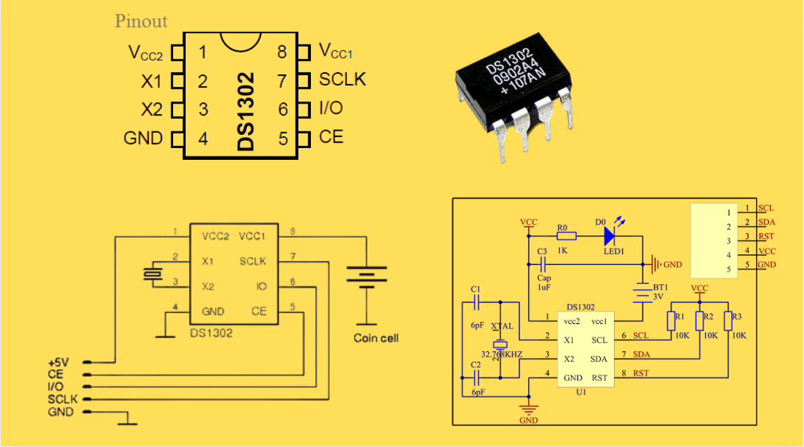
DS1302 RTC: Datasheet,Attributes,Features,Applications
As a low-power device widely used in electronic equipment, the DS1302 is centered on accurate real-time clock/calendar recording functions. It supports full-dimensional tracking of seconds, minutes, hours, days, weeks, months, and years, features automatic leap year compensation, and is compatible w...
-
2025 / 07 / 30
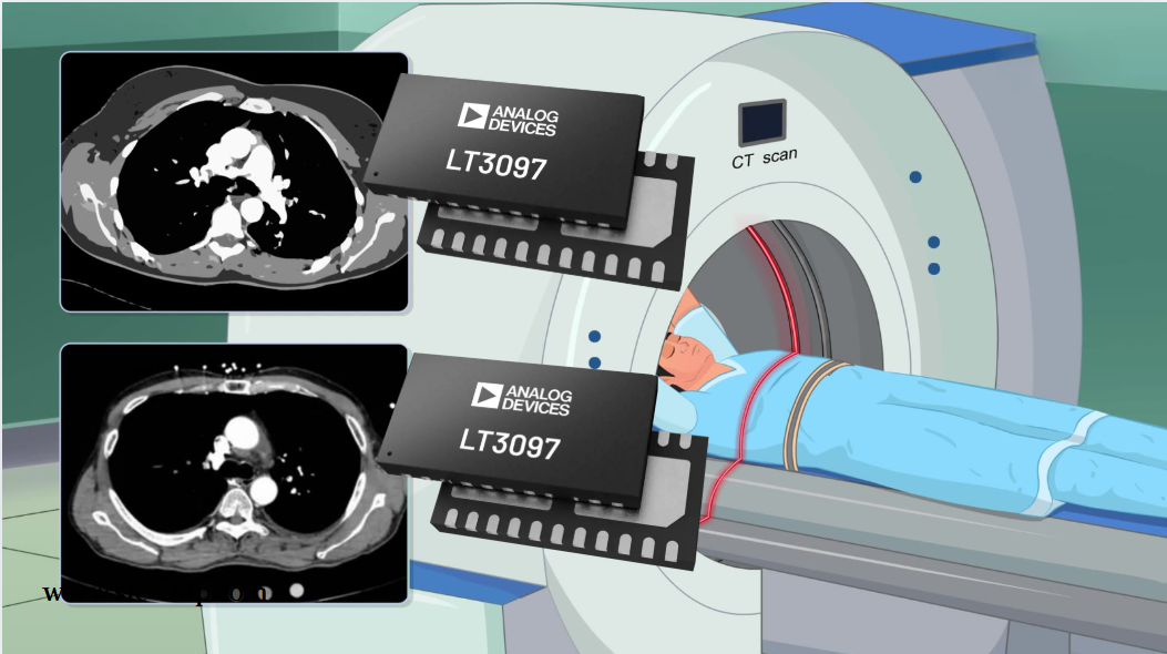
LT3097 Dual 500 mA, positive/negative, ultralow noise, ultrahigh PSRR low dropout linear regulator
The LT3097 is a dual, positive and negative, high-performance, low-dropout linear regulator featuring Analog Devices, Inc., ultralow noise and ultra-high power supply rejection ratio (PSRR) architecture for powering noise-sensitive applications. Each regulator delivers up to 500 mA with a typical 26...
-
2025 / 07 / 28
What is a Digital Integrated Circuit?
In the fast - paced world of modern electronics, digital integrated circuits (ICs) are the unsung heroes that power everything from our smartphones and laptops to complex supercomputers and industrial control systems. But what exactly is a digital integrated circuit?...
-
2025 / 07 / 25
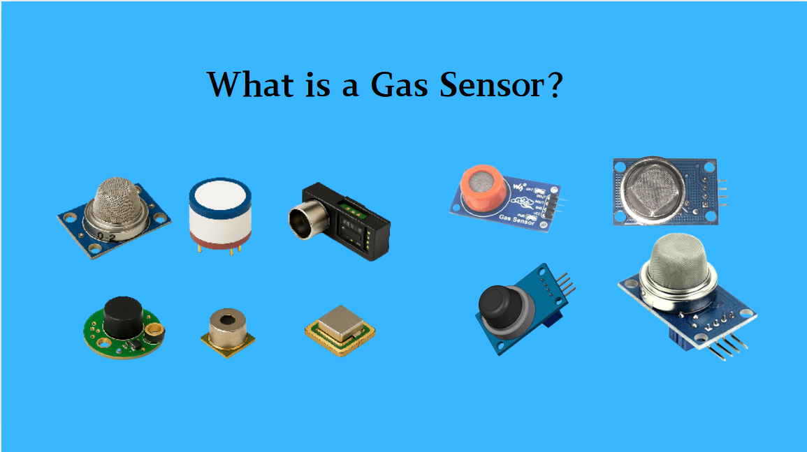
What is a Gas Sensor?
A gas sensor is a device that can convert information such as the composition and concentration of gas into electrical signals recognizable by electronic equipment. It is like the "olfactory organ" of an electronic system, capable of acutely detecting the presence of specific gases in the environmen...
-
2025 / 07 / 24
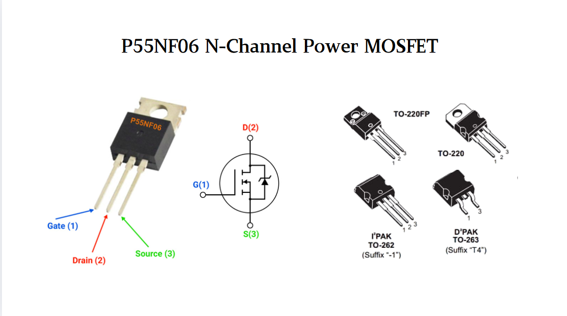
P55NF06 N-Channel Power MOSFET: Everything You Need To Know
In the vast landscape of semiconductor devices, MOSFETs (Metal - Oxide - Semiconductor Field - Effect Transistors) play a pivotal role, especially in power electronics. Among the numerous MOSFET models available, the P55NF06 stands out for its unique combination of features, making it suitable for a...
-
2025 / 07 / 23
Operational Amplifier Filters: A Comprehensive Analysis from Fundamentals to Applications
In electronic systems, the purity and accuracy of signals directly determine the performance of devices. Electronic filters composed of operational amplifiers (op-amps) have become a "bridge" connecting original signals and valid information, thanks to their ability to precisely filter signal freque...
-
2025 / 07 / 19
Broadcom BCM5714CKPB: Featrues,Applications,Datasheet And Advantages
When it comes to reliable, high-performance network connectivity in enterprise and industrial systems, the Broadcom BCM5714CKPB stands as a standout solution. This dual-port Gigabit Ethernet controller, developed by Broadcom—a leader in semiconductor innovation—combines robust features, versatile co...
-
2025 / 07 / 15
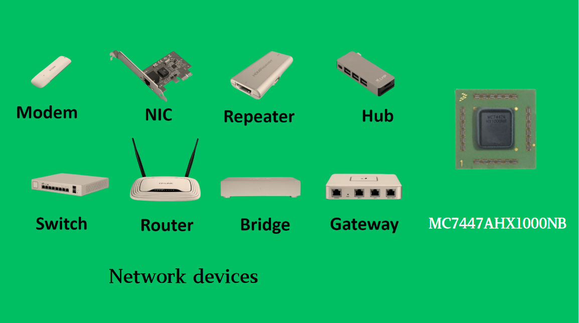
MC7447AHX1000NB: Technical Analysis and Applications of a High-Performance PowerPC Architecture Proc
In the field of embedded computing and network systems, the performance, energy efficiency, and compatibility of processors are often crucial to the success of a design. The MC7447AHX1000NB launched by NXP (formerly Freescale), as an important member of the MPC7447A series, has become an ideal choic...
-
2025 / 07 / 14
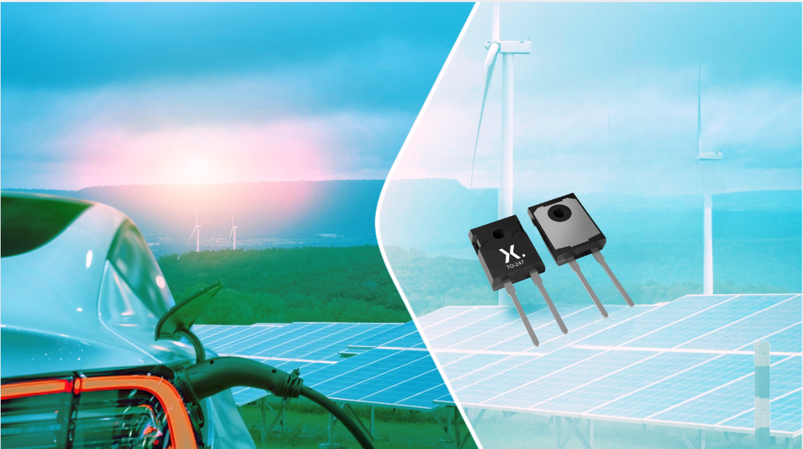
Nexperia Unveils New 1200V/20A SiC Schottky Diodes to Empower Efficient Industrial Power Innovations
Nexperia recently announced the addition of two new 1200V, 20A silicon carbide (SiC) Schottky diodes—PSC20120J and PSC20120L—to its power electronics portfolio, further expanding its product landscape in high-performance semiconductors. Specifically designed to address the increasingly stringent dem...
-
2025 / 07 / 09
CD4007: A Comprehensive Analysis of a Multifunctional CMOS Integrated Circuit
In the field of modern electronic technology, CMOS (Complementary Metal-Oxide-Semiconductor) integrated circuits have become core components in digital and analog circuit design due to their low power consumption, high integration, and excellent compatibility. As a classic CMOS device, the CD4007 oc...


2000+
Daily average RFQ Volume

30,000,000
Standard Product Unit

2800+
Worldwide Manufacturers

15,000 m2
In-stock Warehouse
 Wishlist (0 Items)