

- RFQ
- BOM
-
Contact Us
Tel: +86-0755-83501315
Email: sales@sic-components.com


- Chinese
- English
- French
- German
- Portuguese
- Spanish
- Russian
- Japanese
- Korean
- Arabic
- Irish
- Greek
- Turkish
- Italian
- Danish
- Romanian
- Indonesian
- Czech
- Afrikaans
- Swedish
- Polish
- Basque
- Catalan
- Esperanto
- Hindi
- Lao
- Albanian
- Amharic
- Armenian
- Azerbaijani
- Belarusian
- Bengali
- Bosnian
- Bulgarian
- Cebuano
- Chichewa
- Corsican
- Croatian
- Dutch
- Estonian
- Filipino
- Finnish
- Frisian
- Galician
- Georgian
- Gujarati
- Haitian
- Hausa
- Hawaiian
- Hebrew
- Hmong
- Hungarian
- Icelandic
- Igbo
- Javanese
- Kannada
- Kazakh
- Khmer
- Kurdish
- Kyrgyz
- Latin
- Latvian
- Lithuanian
- Luxembou..
- Macedonian
- Malagasy
- Malay
- Malayalam
- Maltese
- Maori
- Marathi
- Mongolian
- Burmese
- Nepali
- Norwegian
- Pashto
- Persian
- Punjabi
- Serbian
- Sesotho
- Sinhala
- Slovak
- Slovenian
- Somali
- Samoan
- Scots Gaelic
- Shona
- Sindhi
- Sundanese
- Swahili
- Tajik
- Tamil
- Telugu
- Thai
- Ukrainian
- Urdu
- Uzbek
- Vietnamese
- Welsh
- Xhosa
- Yiddish
- Yoruba
- Zulu
- Kinyarwanda
- Tatar
- Oriya
- Turkmen
- Uyghur
Oscilloscope Probe Amplifiers: The Unsung Heroes of Signal Integrity
In the realm of electronic testing and measurement, oscilloscopes are indispensable tools for visualizing and analyzing electrical signals. However, the quality of measurements hinges not just on the oscilloscope itself, but on the often-overlooked component connecting the device to the circuit under test: the oscilloscope probe amplifier. These specialized amplifiers serve as the critical interface, ensuring that weak, high-frequency, or noise-prone signals are accurately transmitted to the oscilloscope while preserving signal integrity. This article explores the principles, types, key specifications, and practical applications of oscilloscope probe amplifiers.
The Role of Oscilloscope Probe Amplifiers
Oscilloscope probe amplifiers bridge the gap between the circuit under test (CUT) and the oscilloscope’s input stage. Their primary functions include:
Signal Amplification: Boosting weak signals (e.g., microvolt-level sensor outputs) to levels detectable by the oscilloscope, which typically requires millivolt to volt-range inputs.
Impedance Matching: Isolating the CUT from the oscilloscope’s input impedance to prevent loading effects. A high input impedance (often 1 MΩ or 50 Ω) ensures minimal current draw from the CUT, avoiding signal distortion.
Frequency Compensation: Extending the measurement bandwidth by compensating for capacitive or inductive loading from probe cables, which can otherwise attenuate high-frequency signals.
Noise Reduction: Suppressing environmental interference (e.g., electromagnetic interference, EMI) and internal noise to preserve signal fidelity, especially critical for low-amplitude signals.
Types of Oscilloscope Probe Amplifiers
Oscilloscope probe amplifiers are categorized based on their design, bandwidth, and application scenarios. The most common types include:
1. Passive Probe Amplifiers
Passive probes rely on resistive and capacitive networks (no active components like transistors or op-amps) to condition signals. They are:
Cost-effective and rugged, suitable for general-purpose measurements (e.g., digital logic signals, power supply ripples).
Limited by bandwidth (typically up to 500 MHz) due to inherent capacitive loading.
Characterized by fixed attenuation (e.g., 10:1, meaning the signal is attenuated by a factor of 10 before reaching the oscilloscope), which reduces loading but requires the oscilloscope to account for the attenuation ratio.
2. Active Probe Amplifiers
Active probes incorporate operational amplifiers or field-effect transistors (FETs) in the probe tip to amplify signals and improve impedance matching. Key features include:
High bandwidth (up to several GHz), making them ideal for high-speed digital signals (e.g., PCIe, HDMI) or RF measurements.
Low input capacitance (often <1 pF) to minimize loading on high-frequency circuits.
Power requirements: Most active probes need external power (via the oscilloscope or a separate supply) to operate the internal amplifiers.
3. Current Probe Amplifiers
Current probes measure electrical current by converting it to a voltage signal using inductive or resistive sensing. They are:
Non-intrusive (clamp-style designs avoid breaking the circuit) or in-line (series resistors for low currents).
Used for power electronics (e.g., motor drives, battery testing) to analyze current waveforms, ripple, and transients.
Available in AC-only or AC/DC models, with bandwidths ranging from DC to 1 GHz.
4. Differential Probe Amplifiers
Differential probes measure the voltage difference between two points (rather than between a signal and ground), making them essential for:
High-common-mode-voltage environments (e.g., power inverters, motor controllers), where ground loops or noise could corrupt single-ended measurements.
Balanced signals (e.g., Ethernet, USB 3.0) and differential signaling standards.
Key specs: High common-mode rejection ratio (CMRR, often >60 dB at 50 Hz) and common-mode voltage range (up to several kV).
Key Specifications for Oscilloscope Probe Amplifiers
Selecting the right probe amplifier depends on matching its specifications to the measurement requirements:
1. Bandwidth
The range of frequencies the probe can accurately transmit, typically specified as the -3 dB point. For example:
A 100 MHz probe is sufficient for audio or low-speed digital signals.
A 2 GHz probe is needed for high-speed serial buses (e.g., USB4, DDR5).
2. Input Impedance
Resistive component: 1 MΩ is standard for passive probes (matching most oscilloscopes’ input impedance), while active probes may offer 50 Ω for high-frequency applications.
Capacitive component: Lower capacitance (e.g., <10 pF) reduces loading on high-frequency circuits, critical for preserving fast edges in digital signals.
3. Attenuation Ratio
Passive probes often use 10:1 attenuation to reduce loading, while active probes may offer 1:1 (no attenuation) for weak signals or 10:1 for higher dynamic range.
4. Noise Performance
Voltage noise density (e.g., nV/√Hz) quantifies the probe’s inherent noise. Lower noise is critical for measuring small signals (e.g., sensor outputs, neural signals in biomedical applications).
5. Common-Mode Rejection Ratio (CMRR)
For differential probes, CMRR measures the ability to reject signals common to both inputs (e.g., power line noise). A higher CMRR (e.g., 80 dB at 1 MHz) ensures accurate differential measurements in noisy environments.
6. Maximum Input Voltage
The highest voltage the probe can safely handle without damage. Passive probes may tolerate 1000 V peak, while high-voltage differential probes can handle up to 10 kV or more.
Popular Oscilloscope Probe Amplifier Models
Several models have become industry standards due to their reliability and performance across applications:
Tektronix P6139B (Passive Probe)
Bandwidth: 500 MHz
Attenuation: 10:1
Input impedance: 10 MΩ || 9 pF
Ideal for general-purpose measurements, including digital logic and analog signals, with rugged construction for lab and field use.
Keysight N2891A (Active Probe)
Bandwidth: 2 GHz
Input impedance: 1 MΩ || 0.9 pF
Features low noise (3.5 nV/√Hz) and 1:1/10:1 switchable attenuation, making it suitable for high-speed digital and RF measurements.
Rigol RP1003C (Current Probe)
Bandwidth: DC to 30 MHz
Current range: ±10 A (peak)
Clamp-style design for non-intrusive current measurements in power circuits, with a built-in amplifier converting current to 100 mV/A (e.g., 1 A = 100 mV).
Teledyne LeCroy DP02500 (Differential Probe)
Bandwidth: 2.5 GHz
Common-mode voltage range: ±500 V
CMRR: >80 dB at 100 MHz, ideal for measuring differential signals in high-voltage environments like motor drives or power converters.
Siglent SP2010 (Passive Probe)
Bandwidth: 100 MHz
Attenuation: 10:1
Budget-friendly option for educational labs or basic electronics testing, with adjustable compensation for optimal frequency response.
Practical Applications and Best Practices
Applications
Digital Design: Active or high-bandwidth passive probes analyze signal integrity (e.g., rise time, overshoot) in microprocessors or FPGAs.
Power Electronics: Current probes measure inrush currents, while differential probes analyze voltage across switches (e.g., MOSFETs, IGBTs).
Biomedical Engineering: Low-noise active probes amplify 微弱生理信号 (e.g., ECG, EMG) without introducing noise.
RF Testing: 50 Ω active probes with GHz-range bandwidth characterize RF circuits, antennas, and wireless transceivers.
Best Practices
Compensation: For passive probes, use the oscilloscope’s calibration signal (typically a 1 kHz square wave) to adjust the probe’s compensation capacitor, ensuring flat frequency response.
Cable Management: Keep probe cables short to minimize noise and signal degradation; use shielded cables to reduce EMI.
Grounding: Connect the probe’s ground lead as close to the CUT as possible to avoid ground loops, which can introduce noise.
Overvoltage Protection: Ensure the probe’s maximum input voltage exceeds the CUT’s signal amplitude to prevent damage.
Conclusion
Oscilloscope probe amplifiers are far more than mere connectors—they are precision instruments that define the quality of measurements in electronic testing. Whether analyzing high-speed digital signals, measuring power currents, or capturing faint biomedical signals, the right probe amplifier ensures accuracy, minimizes distortion, and extends the capabilities of the oscilloscope. By understanding the types, specifications, and best practices, engineers and technicians can select probes that unlock the full potential of their measurement systems, enabling breakthroughs in design, troubleshooting, and research.
https://www.sic-components.com/amplifierscategory-1


Hot Products
View More-

M4Q045-DA05-87 ebm-papst Inc.
-
LE614NGHHR-029 ebm-papst Inc.
-

F-336-1 Aearo Technologies LLC, a 3M company
-
2170-4-7320 ebm-papst Inc.
-
64442-1-7612 ebm-papst Inc.
-

FMG-3 Essentra Components
-
51025-2-4053 ebm-papst Inc.
-
9621-2-4013 ebm-papst Inc.
-
F-310-C8012 Aearo Technologies LLC, a 3M company
-

605-15-1573 ebm-papst Inc.
-
2101-4-7320 ebm-papst Inc.
-
FGA-120 Essentra Components
Related Blogs
-
2025 / 07 / 28
What is a Digital Integrated Circuit?
In the fast - paced world of modern electronics, digital integrated circuits (ICs) are the unsung heroes that power everything from our smartphones and laptops to complex supercomputers and industrial control systems. But what exactly is a digital integrated circuit?...
-
2025 / 07 / 25
What is a Gas Sensor?
A gas sensor is a device that can convert information such as the composition and concentration of gas into electrical signals recognizable by electronic equipment. It is like the "olfactory organ" of an electronic system, capable of acutely detecting the presence of specific gases in the environmen...
-
2025 / 07 / 24
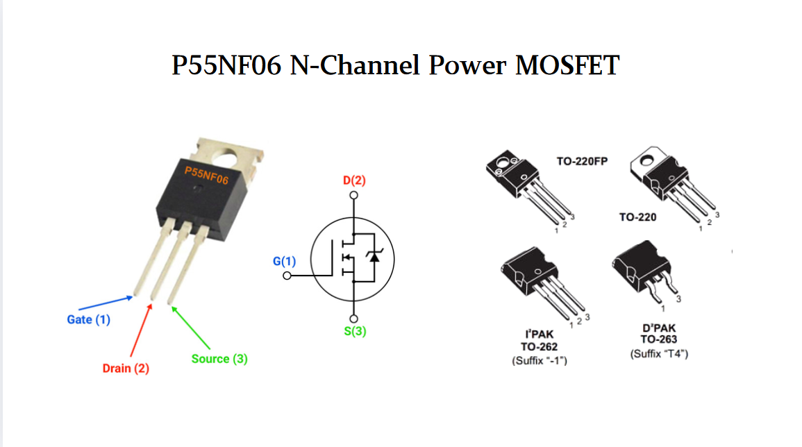
P55NF06 N-Channel Power MOSFET: Everything You Need To Know
In the vast landscape of semiconductor devices, MOSFETs (Metal - Oxide - Semiconductor Field - Effect Transistors) play a pivotal role, especially in power electronics. Among the numerous MOSFET models available, the P55NF06 stands out for its unique combination of features, making it suitable for a...
-
2025 / 07 / 23
Operational Amplifier Filters: A Comprehensive Analysis from Fundamentals to Applications
In electronic systems, the purity and accuracy of signals directly determine the performance of devices. Electronic filters composed of operational amplifiers (op-amps) have become a "bridge" connecting original signals and valid information, thanks to their ability to precisely filter signal freque...

-
2025 / 07 / 19
Broadcom BCM5714CKPB: Featrues,Applications,Datasheet And Advantages
When it comes to reliable, high-performance network connectivity in enterprise and industrial systems, the Broadcom BCM5714CKPB stands as a standout solution. This dual-port Gigabit Ethernet controller, developed by Broadcom—a leader in semiconductor innovation—combines robust features, versatile co...

-
2025 / 07 / 15
MC7447AHX1000NB: Technical Analysis and Applications of a High-Performance PowerPC Architecture Proc
In the field of embedded computing and network systems, the performance, energy efficiency, and compatibility of processors are often crucial to the success of a design. The MC7447AHX1000NB launched by NXP (formerly Freescale), as an important member of the MPC7447A series, has become an ideal choic...
-
2025 / 07 / 14
Nexperia Unveils New 1200V/20A SiC Schottky Diodes to Empower Efficient Industrial Power Innovations
Nexperia recently announced the addition of two new 1200V, 20A silicon carbide (SiC) Schottky diodes—PSC20120J and PSC20120L—to its power electronics portfolio, further expanding its product landscape in high-performance semiconductors. Specifically designed to address the increasingly stringent dem...
-
2025 / 07 / 09
CD4007: A Comprehensive Analysis of a Multifunctional CMOS Integrated Circuit
In the field of modern electronic technology, CMOS (Complementary Metal-Oxide-Semiconductor) integrated circuits have become core components in digital and analog circuit design due to their low power consumption, high integration, and excellent compatibility. As a classic CMOS device, the CD4007 oc...

-
2025 / 07 / 07
Understanding IC 7408: A Fundamental Component in Digital Logic Design
In the vast and intricate realm of digital electronics, integrated circuits (ICs) serve as the building blocks that enable the creation of complex and powerful systems. Among these, the IC 7408 holds a special place as a fundamental component in digital logic design. This article aims to provide a c...
-
2025 / 07 / 04
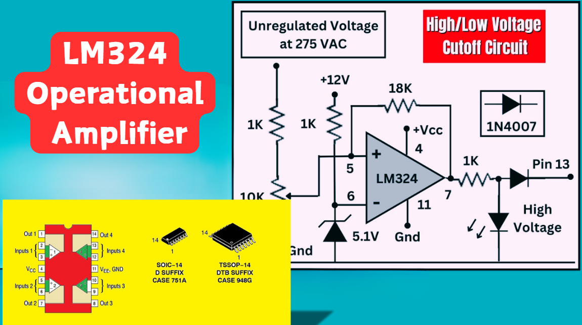
LM324 Operational Amplifier Comprehensive Guide: Pins, Applications, Packaging, and Datasheet
The LM324 is a low-cost integrated circuit featuring four independent operational amplifiers (op-amps), renowned for its wide voltage adaptability, low power consumption, and high reliability in industrial and consumer electronics. With a single-supply voltage range of 3V to 32V (or dual-supply rang...

2000+
Daily average RFQ Volume

30,000,000
Standard Product Unit

2800+
Worldwide Manufacturers

15,000 m2
In-stock Warehouse
 Wishlist (0 Items)